
Some gear manufacturers are: www.bostgear.com, www.putnamprecisionmolding.com, www.huco.com
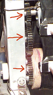
Examples of some gears:
The gears in your kit may be slightly different.
If gears are metric: To translate metric module numbers into US nomenclature, use the following equation: m = D/N=1/P where m is the module number, D is the pitch diameter, N is the number of teeth and P is diametral pitch. Module 1 gears are roughly approximate to a diametral pitch of 24 (exact is 25.4). However, mod 1 gears will NOT work with 24 diametral pitch gears or racks!!!
For gears to mesh properly they need to be aligned in the same plane. Be careful to align both shafts such that they are parallel. (This is done easily by mounting a piece of Delrin on the mill and drilling two holes for shafts without changing the setup.)
The gears should mesh together such that the tooth of one gear penetrates into the meshing gear about 70% of the total tooth height.
The speed reduction or increase is equal to the ratio of the gear diameters (or the ratio of the number of teeth.)
Gears can be used to translate power from one shaft to another with very little change in torque or speed. There will be a slight reduction as every gear mesh is between 85% and 95% efficient,
To make a system with a large speed or torque reduction, you should make gear trains in the same way as in the Polaroid motor assembly.
To mount the gears, use the pitch diameter to find the center distance.
To modify, you can use the following tools: Drill (to make thru hole larger)
You should not use: Shear, Notcher, Punch, or any other power tool
Driving a conveyor with the Green Maxon Motor