The task for this sponsored research project is to create a mechanical interface standard will enable a robotic subassembly, such as a wrist, to be easily changed, without requiring recalibration of the robot. The wrist would mate to a standard plate. A similar master plate would be located at the robot manufacturer, and each subassembly would be calibrated with respect to the mounting plate master. Thus when a replacement subassembly is delivered to the factory, it comes with a set of calibration coefficients with respect to the mounting plate master, and it can be “plugged into place and start working”. Thus should a subassembly fail during use, it could be “unplugged” and a new subassembly can be “plugged in” and used without having to recalibrate it to the line.
To achieve this standard, kinematic coupling elements, six degree of freedom mechanical contacts, will be used. Prof. Slocum has been developing kinematic coupling technology for the past 15 years (see appendix for an extensive list of references and patents), and his designs could be used in a system and method to enable subassemblies or entire robots to be rapidly installable, and hence interchangeable, on the factory floor
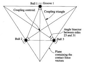
Kinematic couplings have been used for over a century to precisely locate two parts with respect to each other. A common form is the three-groove kinematic coupling should schematically in Figure 1 and as a microscope assembly interface in Figure 2.
|
|
|
| Figure 1 Basic layout of a kinematic coupling | Figure 2 Kinematic couplings used as assembly interface elements for a new type of microscope structure |
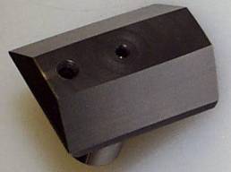
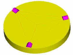
Historically, however, the six points of contact that give a kinematic coupling its amazing part-per-million repeatability also limit the loads that it can support; however, Slocum developed a “canoe-ball” shape that emulates the contact region of a large ball, e.g., a 500 mm diameter ball, in a small element, on the order of 25 mm across. This is accomplished by means of precision CNC cylindrical grinding to create this “virtual ball”. A Canoe Ball is shown in Figure 3, and installed in a test fixture in Figure 4. Figure 5 shows the repeatability data, an astonishing 0.1 nanometers radial on a 0.2 m diameter coupling.
|
|
|
|
Figure 3 25 mm Canoe Ball coupling element with 250 mm surface radii of curvature |
Figure 4 0.2 m diameter Canoe Ball test system |
|
|
|
Figure 5 Canoe Ball kinematic coupling radial repeatability experimental results. Note that the instrumentation error was on the order of 0.05 microns. |
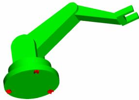
It is proposed that ABB, a major supplier of industrial robots for the automotive industry, and Prof. Slocum and one of his graduate students work together to develop a kinematic coupling system and method that would enable a subassembly to be delivered to the factory with a set of calibration coefficients with respect to a mounting plate master, so it can be “plugged into place and start working”. Should the subassembly fail during use, it could be “unplugged” and a new machine can be “plugged in” and used without having to recalibrate it to the line. This concept is shown in Figures 6, 7, and 8 in terms of an entire robot, but would at first be developed for a subassembly such as a robot wrist, which is the most frequently damaged subassembly.
Note that Ford Motor Company will separately be funding research to achieve robot interchangeability, as shown in Figs. 6, 7, and 8. It is anticipated that ABB and Ford will cooperate on this research.
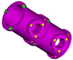
Note that in addition to the kinematic mounting plate, a method to couple and align drive shafts through the coupling is also needed. In the most basic form, such a coupling could be a simple helical coupling with a split collar attachment, which is activated by tightened bolts.
|
|
|
|
Figure 6 Proposed standard “Canoe-Ball” base plate interface |
Figure 7 Proposed standard “Vee-Groove” robot interface |
 |
|
Figure 8 Canoe-Ball base plates have been precisely located on a manufacturing line, and now robots are being “plugged in” |
In order to accomplish this research, funding for the first year is requested in which a graduate student will design and conduct preliminary experiments to verify the feasibility of this concept, and then work with ABB engineers to create parts to retrofit an existing ABB robot. This is very much a team effort, where MIT can provide design ideas and details, but ABB must provide the equipment and the facilities to conduct tests that are deemed meaningful. If the concept proves viable, then a second year of funding will be requested to generalize the design method and to create tools to help teach ABB engineers how to use this design methodology in other areas as well. Many of the tasks to feasibility can be run concurrently as noted by (C):
|
Task |
Duration |
Responsibility |
|
Identify robot, gather data, and learn about the design space |
July 1-August 28 |
ABB/MIT |
|
Student at ABB to brainstorm with engineers |
August 29-31 |
ABB/MIT |
|
Slocum meets team at ABB for mtg. To finalize goals and tasks |
Sept. 1 |
ABB/MIT |
|
Concept development and bench level tests |
Sept. 5-Dec. 1 |
MIT |
|
Design review |
Dec. 4 |
ABB/MIT |
|
Concept refine and develop test part drawings |
Dec. 5-Jan 15 |
MIT |
|
Make parts |
Jan 15-March 1 |
ABB |
|
Prepare test plan |
Jan 15-March 16 |
ABB/MIT |
|
Conduct tests on robot (at ABB or MIT, to be determined) |
March 19-23 |
ABB/MIT |
|
Decision on production worthiness |
March 26-30 |
ABB/MIT |
|
Develop production drawings |
April 2-June 1 |
ABB/MIT |
|
Develop methods to transfer kinematic design capability to ABB engineers, and plan for 2nd year. |
June 4-29 |
MIT |
It is anticipated that the above R&D activities will result in the following deliverables:
Detailed design guidelines for creating a precision interface (e.g., kinematic coupling) between a robot wrist and the robot, where:
The robot is calibrated in the factory using a “master wrist”.
Wrists are calibrated in the factory
Any wrist can be coupled to any robot and the calibration coefficients will be valid, because of the preciseness of the interface
Web site for kinematic coupling design procedures
Test data to verify the coupling system
Appendix: Kinematic Coupling References
1. Slocum, A. H. "Kinematic Couplings for Precision Fixturing - Part I - Formulation of Design Parameters," Precision Eng., Vol. 10, No. 2, April 1988, pp 85-91.
2. Slocum, A. H. and Donmez, A., "Kinematic Couplings for Precision Fixturing - Part II - Experimental Determination of Repeatability and Stiffness," Precision Eng., Vol. 10, No. 3, July 1988, pp 115-122.
3. Slocum, A. H. "Design of Three-Groove Kinematic Couplings," Precision Eng., Vol. 14, No. 2, April 1992, pp 67-76.
4. Battles, A.E., Linder, B. M., Chang, K.W., Slocum, A.H., "The Design of a Precision Bilaminar Resonating Transducer Assembly Tool", Precision Eng., Vol. 15, No. 4, Oct. 1993, pp 248-257.
5. Schmiechen, P., Slocum, A.H., "Analysis of Kinematic Systems: a Generalized Approach", Precision Eng., Vol. 19, No. 1, July 1996, pp. 11-18.
6. Pfahnl, A. C., Lienhard V, J. H., Slocum, A.H., “Heat Transfer Enhancing Features for Handler Tray-Type Device Carriers”, IEEE Transactions on Components, Packaging, and Manufacturing Technology Part C: Manufacturing, Vol. 21, No. 4, October 1998.
7. Vallance, R, Slocum, A., "The Design of Split-Groove Kinematic Couplings", submitted to Precision Eng., May 1999.
8. Culpepper, M. L, Slocum, A. H., Shaikh F. Z, "Quasi-Kinematic Couplings For Precision Automotive Assemblies,” To be presented at the 1999 ASME-ICE Fall Technical Conference," Ann Arbor, IN, October, 1999.
9. Culpepper, M. L, Slocum, A. H., Shaikh F. Z, "Quasi-Kinematic Couplings: A Low-Cost Method For Precision coupling of Product Components and the Like in Manufacturing Processes,” To be presented at the 1999 Annual Meeting of the American Society for Precision Engineering, Monterey, CA, November,1999.
10. A. Slocum, D. Braunstein, L. Muller, “Flexural Kinematic Couplings”, #5,678, 944, October 1997
11. A. Slocum, “Method and Apparatus for Locating and Orienting a Part on a Gripper and Transferring it to a Tool while Maintaining Location and Orientation on the Tools”, 5,711,647, January1998
12. A. Slocum, "Kinematic Coupling Fluid Couplings and Method", #5,683,118
13. A. Slocum, et-al, “Modular System”, #5,733,024, March 31, 1998
14. A. Slocum, “Kinematic Coupling Method And System For Aligning Sand Mold Cores And The Like And Other Soft Objects And Surfaces” #5,769,554
15. A. Slocum, D. Braunstein, “Kinematic Coupling for Thin Plates and Sheets and the Like”, #5,915,678, June 29, 1999
[1] Research to be led by Prof. Alexander H. Slocum, Department of Mechanical Engineering, Massachusetts Institute of Technology, 77 Massachusetts Avenue, Room 3-445, Cambridge, MA 02139, 617.253.0012 617-258-6427 (fax) slocum@mit.edu, http://pergatory.mit.edu