 Groove on REX foot_1.jpg |
This picture shows the groove plate placed on the base of the robot. This measurement is the baseline for the other axes. |
 WW on REX foot_1.jpg |
This picture shows the unit in place on the base groove plate. |
 Groove on REX axis1_1.jpg |
Two groove plates for dynamic measurement of axis 1. |
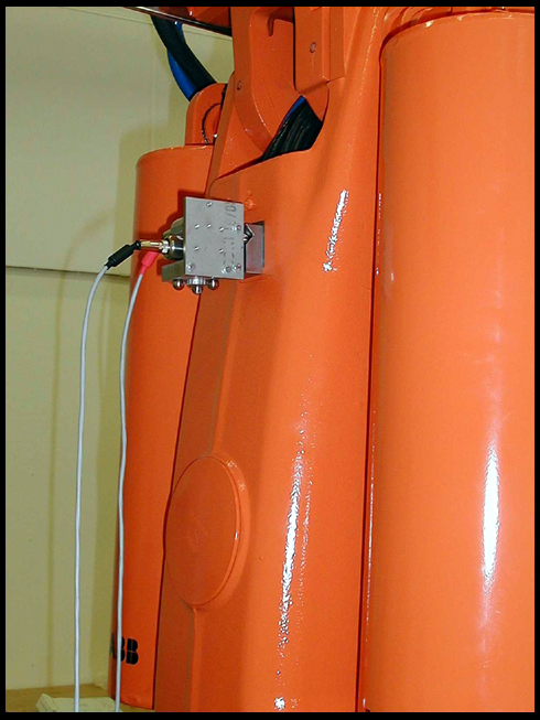
 WW on REX axis1_1.jpg |
Unit in place on the axis 1 groove plates. |
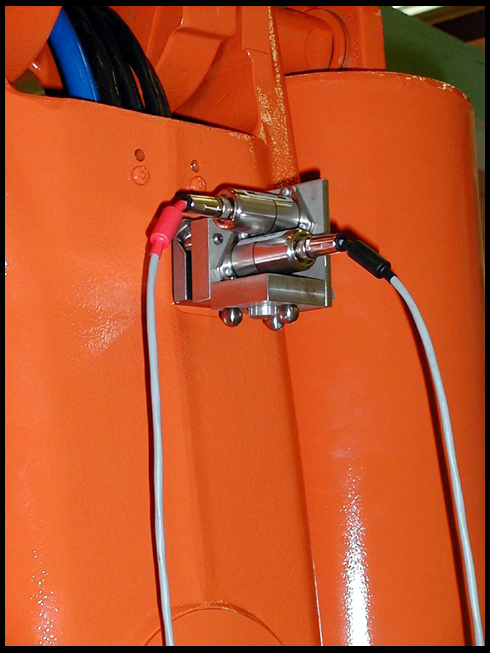
 WW on REX axis1_2.jpg |
Close up of unit in place on the axis 1 groove plates. |
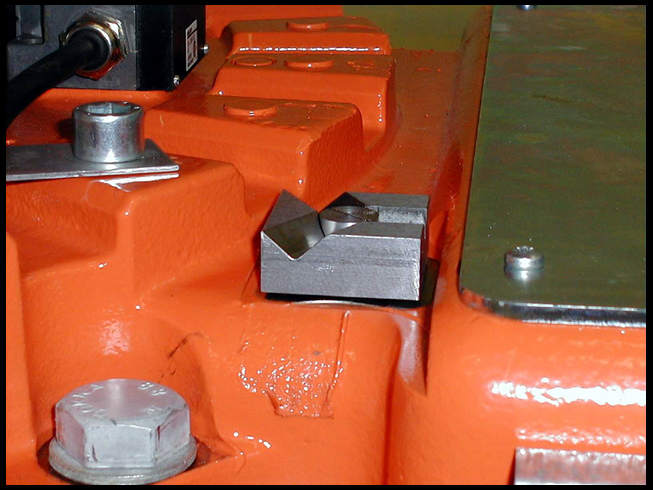
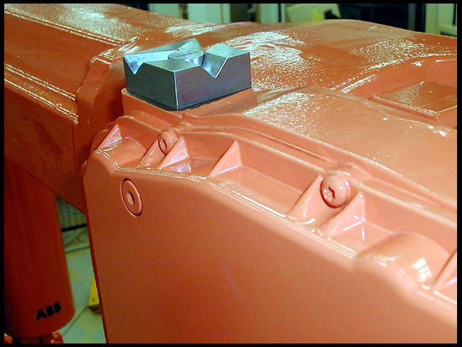
 Groove on REX axis1_2.jpg |
Groove plate on lower arm of robot for measuring axis 2. |
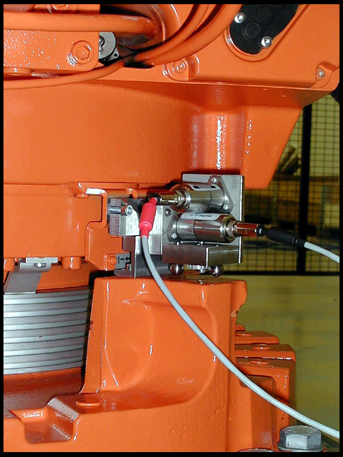
 WW on REX axis2_2.jpg |
Back of unit on axis 2 groove plate. |
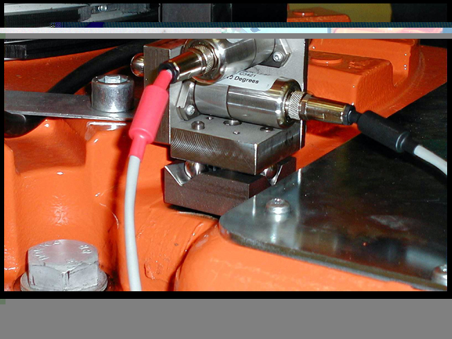
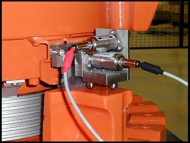
 WW on REX axis2_1.jpg |
Front of unit on axis 2 groove plate. |
 Groove on REX wrist_1.jpg |
Groove plate on robot wrist for measuring axis 3 and 4. |
 WW on REX axis34_1.jpg |
Unit on axis 3/4 groove plate. |
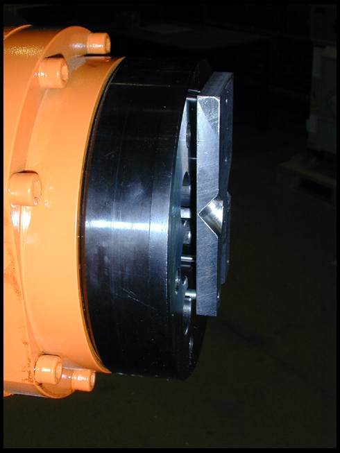
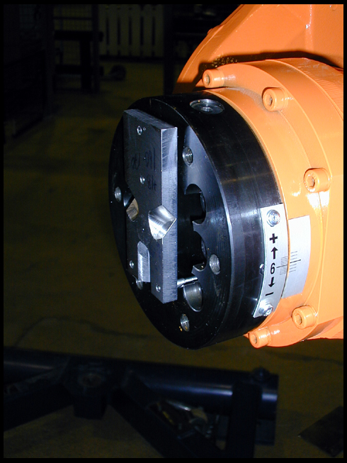
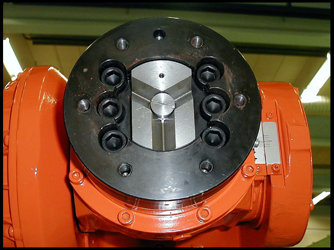
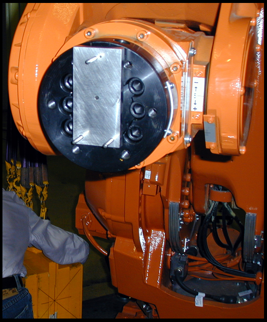
 ABB_three_pin_on_flange_01.jpg |
ABB grooved three pin plate in flange. Used for measuring axes 5 and 6 without requiring modifications to the flange design. |
 ABB_three_pin_on_flange_02.jpg |
ABB grooved three pin plate in flange. |
 ABB_three_pin_on_flange_03.jpg |
ABB grooved three pin plate in flange. |
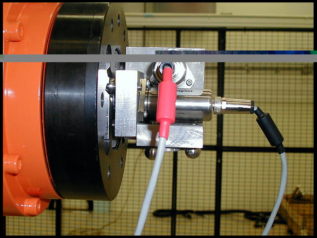
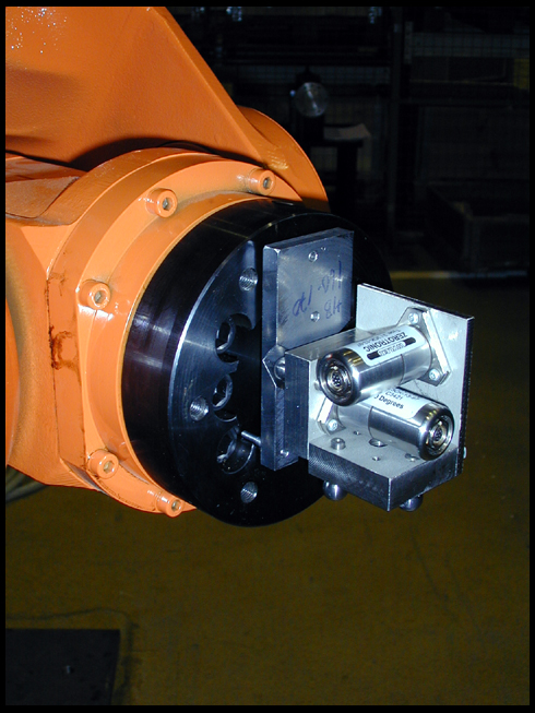 WW_on_3PKC_plate_01.jpg |
Unit on three pin plate in flange. |
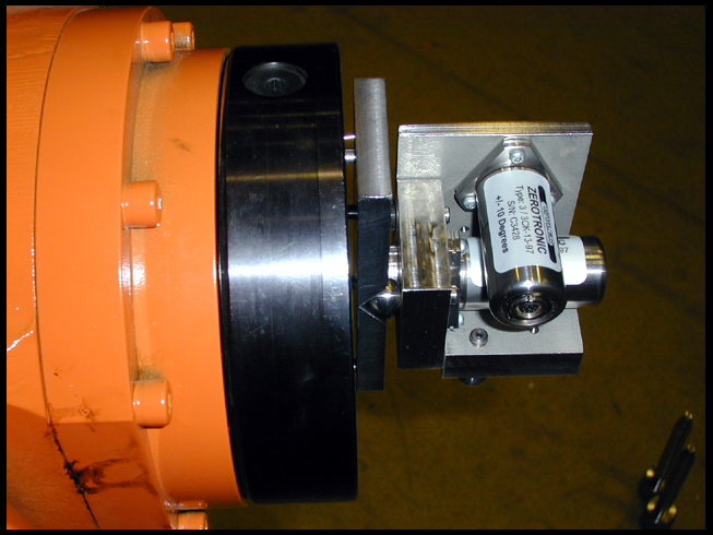
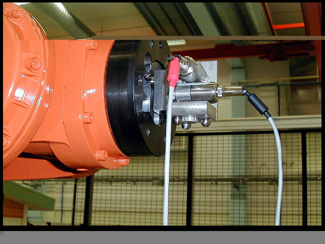
 WW_on_3PKC_plate_02.jpg |
Unit on three pin plate in flange. |
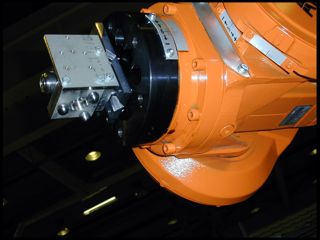
 WW_on_3PKC_plate_03.jpg |
Unit on three pin plate in flange. |
 WW_on_3PKC_plate_04.jpg |
Unit on three pin plate in flange. |
 Groove on REX flange_1.jpg |
Grooved insert plate set in flange. This insert plate would be incorporated into the flange design so a separate plate would not be required. This is the suggested design instead of the three pin design. |
 Groove on REX flange_2.jpg |
Grooved insert plate set in flange. |
 WW on REX flange_1.jpg |
Unit on insert plate in flange to measure axes 5 and 6. |
 WW on REX flange_2.jpg |
Unit on insert plate in flange. |
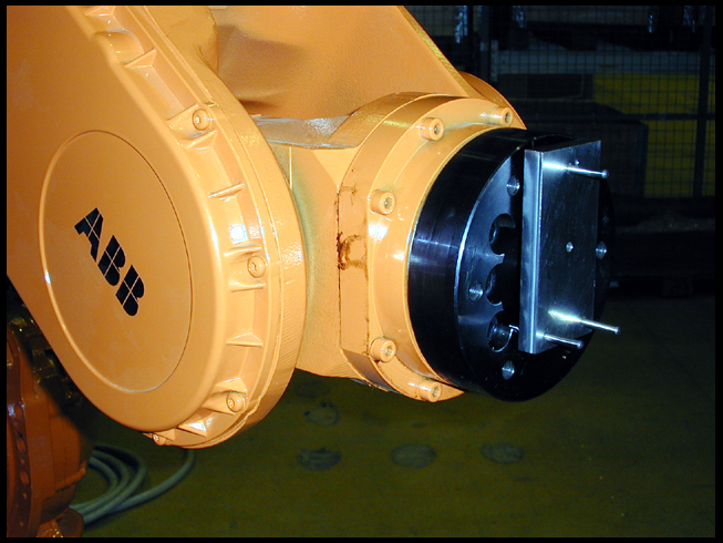 MIT_three_pin_plate_01.jpg |
MIT prototype of three pin interface plate engaged on flange. This plate does not have grooves. |
 MIT_three_pin_plate_02.jpg |
MIT prototype of three pin interface plate engaged on flange. |
