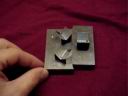
base_inner_disc_1.jpg |
Front view of inner disc prototype. The inner disc represents the moving part of the base (axis 1) Radius of the curve shown is approximately the same as the actual base. |
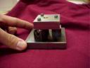
base_inner_disc_2.jpg |
Rear view of the inner disc prototype. |

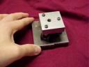
base_outer_edge_1.jpg |
Front view of the outer ring prototype. This ring represents the outer part of the base, which is fixed to the ground. Radius of the curve shown matches the curve on the inner disc. |
base_outer_edge_2.jpg |
Rear view of the outer ring prototype. |
groove_1.jpg |
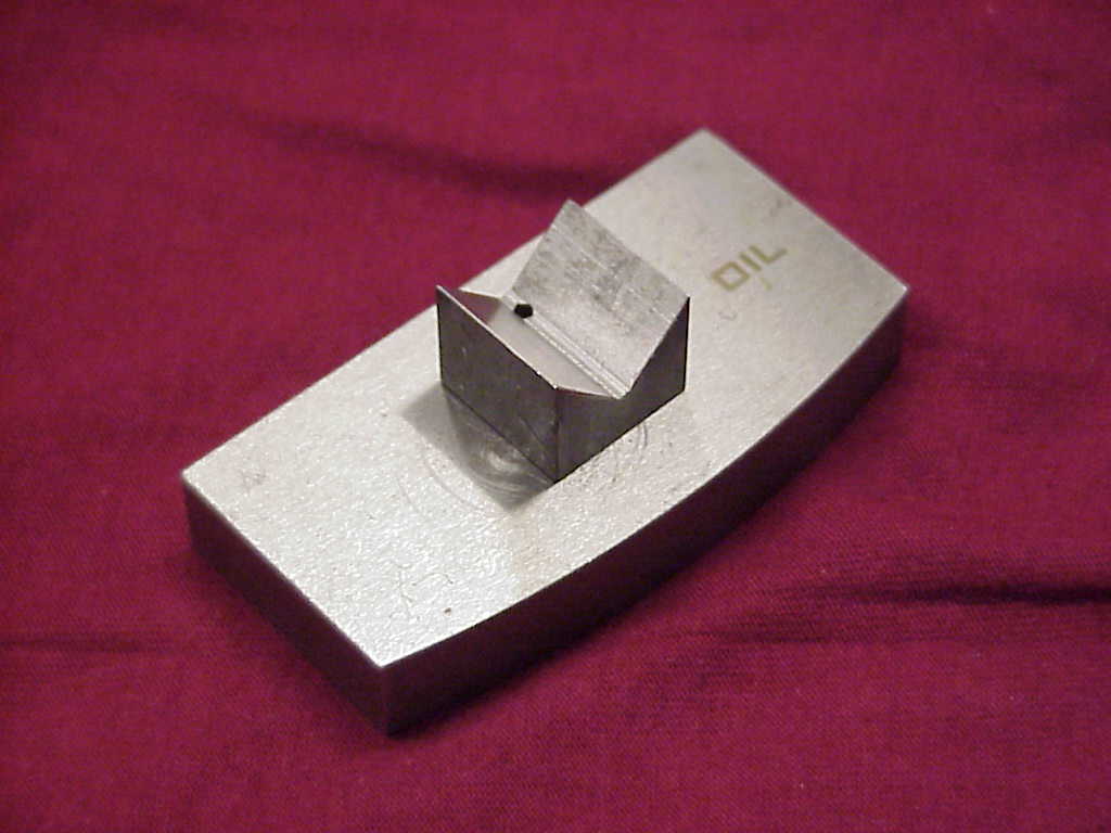
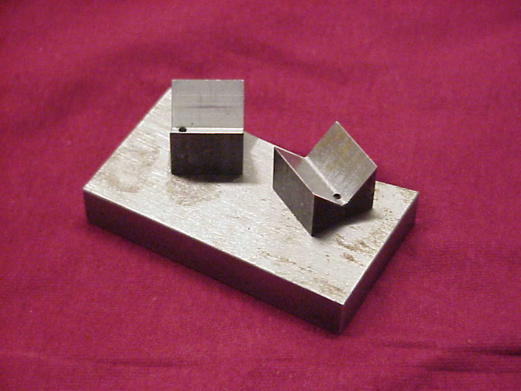
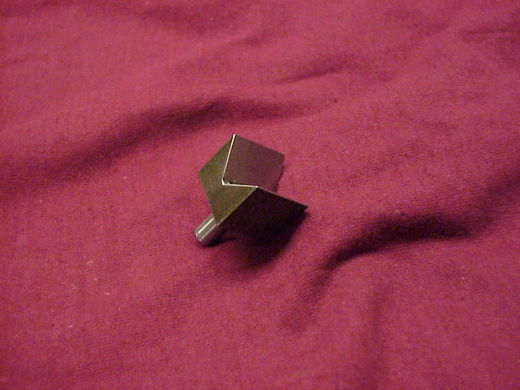
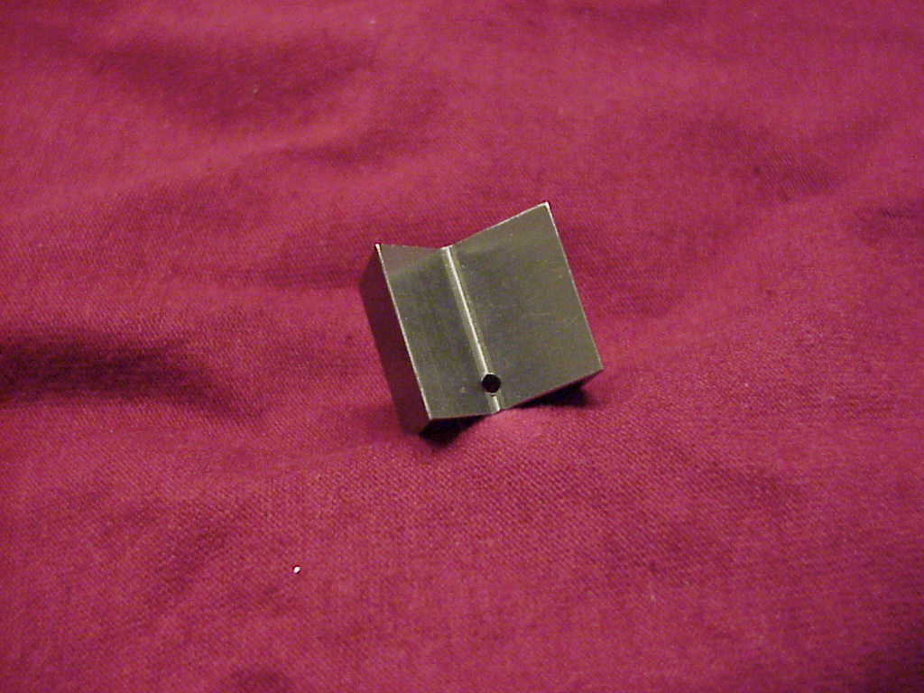
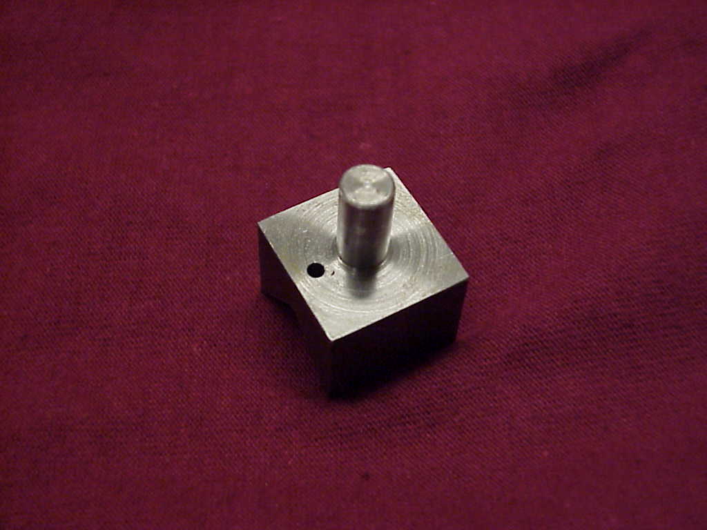
Picture of a groove on a post. |
groove_2.jpg |
Picture of a groove on a post. |
groove_3.jpg |
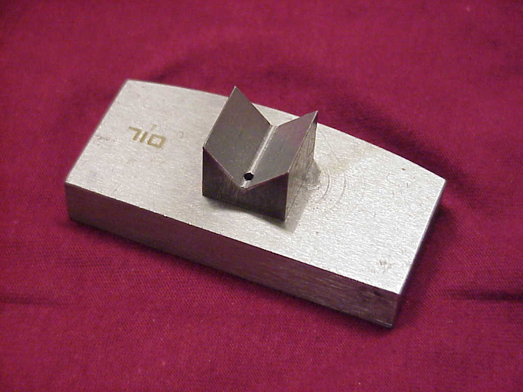
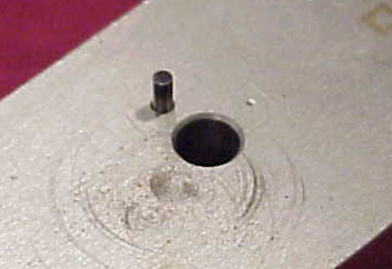
Picture of the bottom of a groove on a post. Note small hole for alignment pin. |
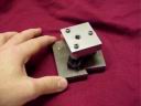
groove_connection.jpg |
This picture shows the groove connection interface on inner disc. The groove post is press fit into the large hole and aligned using the protruding pin. Specific dimensions for these items (ie radius) are not crucial and can be changed for ease of use. |
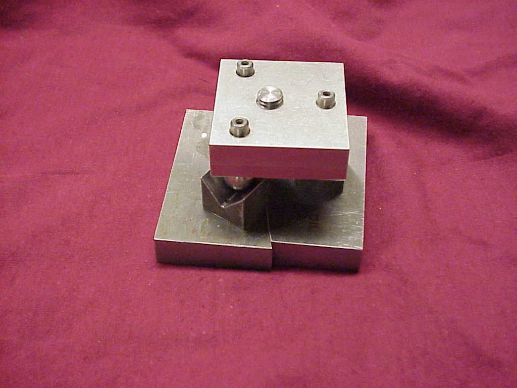
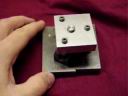
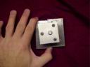
ww_unit_on_base.jpg |
Assembled unit |

 |
Download Solid Works 2000 or IGES CAD Files (No assemblies for IGES) |
Drawings of Parts
 |
Detailed drawings of inner disc in Solid Works 2000 or PDF format |
|
|
Detailed drawings of outer ring in Solid Works 2000 or PDF format |
|
|
Detailed drawings of groove on post in Solid Works 2000 or PDF format |
| Drawings of Wonder Wyler Unit plate available in Side Plate Prototype Section |
Movies
movement_of_base.mpg |
This movie shows the movement of the inner disc to the outer ring without the Wonder Wyler unit in place. These grooves would be the only exposed item on the robot during normal usage. |
unit_moving_no_magnet_1.mpg |
Shows assembled unit in operation without the magnet. Maximum rotation is approximately 5 degrees in either direction. |
unit_moving_no_manget_2.mpg |
Shows assembled unit in operation without the magnet. |
unit_moving_no_magnet_fail.mpg |
Shows assembled unit in operation without the magnet. If the unit is rotated more than 5 degrees either way, the balls on the Wonder Wyler unit will lose contact with the grooves. This failure will invalidate results and possibly damage the unit. A solution is to have physical stops (either magnet or alignment pin). |
complete_unit_moving_1.mpg |
Shows assembled unit in operation with the magnet. With the magnet installed, the unit can only rotate ~2 degree each way. This limited motion can be fixed by reducing the diameter of the magnet or by removing material from the grooves. |
complete_moving_unit_2.mpg |
Shows assembled unit in operation with the magnet. |
Description of Special Parts
The special parts required for this prototype are hardened steel dowel pins, which are available from McMaster-Carr. Two sizes were ordered: 2mm and 5mm diameters. The 2mm diameter pins are part number 91595A203 and are US$16.71 for a package of 100 while the 5mm diameter pins are part number 91595A424 and are US$35 for a package of 100 pins. The McMaster catalog page is here: mcmaster_pins.pdf.
The other special part required for this prototype is a 90 deg. Drill/Mill used to machine the grooves. The mill is a 7/8 inch diameter, 90 degree high speed steel mill. This tool is available from McMaster-Carr as part number 2957A56, at a cost of US$50.51. A copy of the McMaster catalog page for this tool is available here: mcmaster_tool.pdf.
Manufacturing of Prototypes
Manufacturing of the dynamic plate prototypes was the most complex of the prototypes. The outer ring and inner disc required translation of the Solid Works CAD files into CNC instructions using Master CAM software. The following steps were taken for the outer ring and inner disc separately:
-
Material cut to size
-
Material fixtured in CNC milling machine and end surfaces are milled to meet dimensions and smoothed
-
Contoured curve is milled using end mill
-
Holes are drilled through slightly undersized
-
Holes are reamed
-
Part is deburred and polished
-
Dowel pins are pressed into corresponding holes using arbor press
Manufacturing of the groove on a post was performed using a lathe using square stock and standard mill. To increase rotation of the prototype, the groove was later trimmed in a standard mill. The following simplified steps were taken for each groove:
-
Fixture bar stock into lathe
-
Turn end of stock down to 1/4 inch diameter rod
-
Cut off part at top of groove (~16mm)
-
Refixture part in mill
-
Machine 2mm off of a side
-
Refixture part in mill
-
Machine groove into part using 90 deg. drill/mill
-
Drill hole slightly undersized
-
Ream hole to proper dimension
-
Deburr part
-
Press onto corresponding part using arbor press if needed