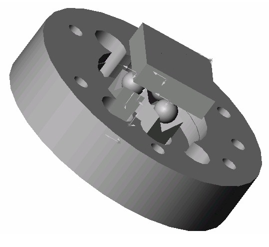
 ball_groove_assembly_v1.jpg |
This view shows the initial concept for the ball and groove coupling inside the flange. |
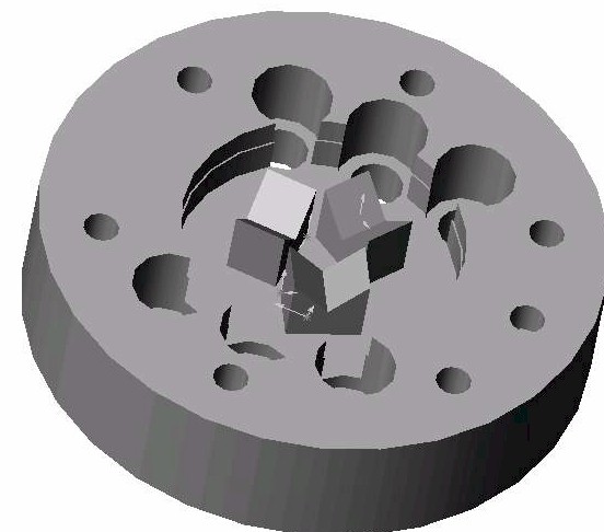 plate_groove.jpg |
Coupling interface on flange are individual grooves press fit into hole in the flange. |
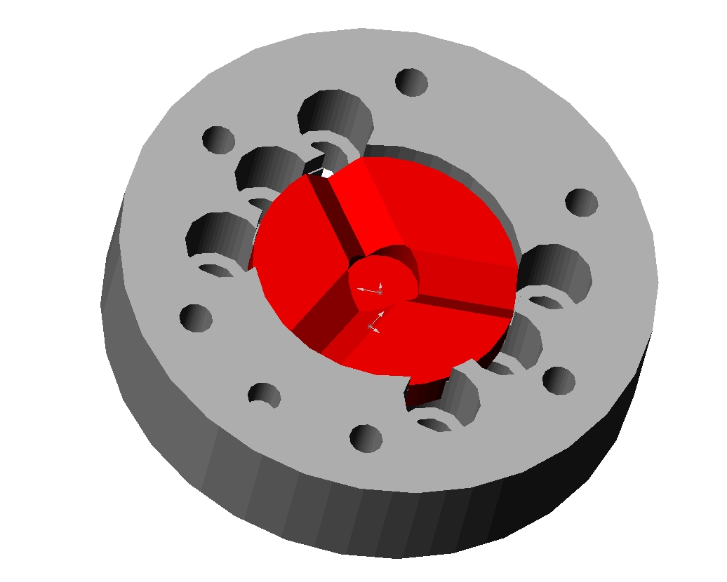
 ball_groove_assembly.jpg |
Current version of flange design. Shows insert plate (red) with grooves in center of flange (light gray). Wonder Wyler unit (dark gray) is shown in position, although balls and magnet cannot be seen. |
 ball_groove_assembly_2.jpg |
Cut-away view of coupling showing only coupling elements. Magnet (green) is attached to a post and is mounted in the center of the coupling. The balls (blue) are grouped on a 20mm radius circle with 120 degrees separating them. |
 groove_insert_in_flange.jpg |
View showing the grooved insert plate in the flange. This insert could feasibly be added to the structure of the flange, removing the extra piece. The insert could be press fit or bolted into place with some geometric features to align the grooves to the control pin hole. |
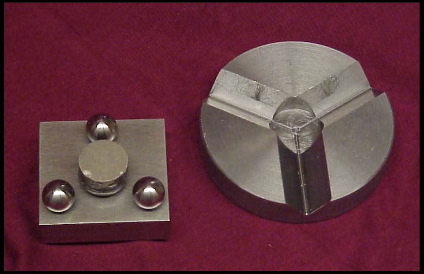 ww_side_with_grooved_insert.jpg |
Prototype of side of Wonder Wyler with three balls and magnet and prototype of grooved insert for flange. Dimensions of prototypes conform to dimensions required by ABB. |
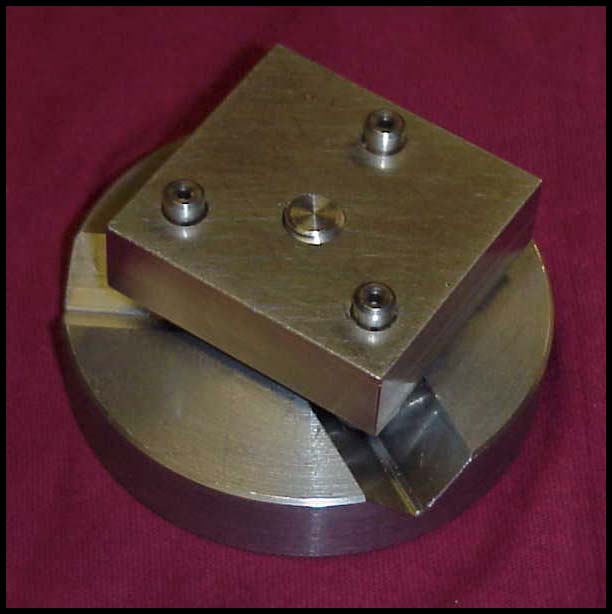 assembled_ww_unit.jpg |
Wonder Wyler unit engaged with grooved insert. The magnet used for the prototype's preload keeps the two pieces together under a considerable force. |
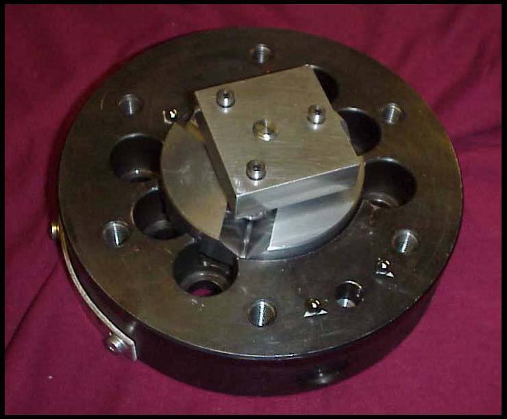 ww_unit_in_flange.jpg |
Wonder Wyler unit and grooved insert plate shown in flange. Using a press fit, the insert plate can be secured to the flange. Insert plate has not been secured in this picture, which causes the insert plate to stick out of the flange. The top surface of the insert plate will sit slightly below the flange surface after a press fit. |
 grooved_flange_insert.jpg |
Basic dimensions shown on grooved flange insert. |

 |
Download Solid Works 2000 or IGES CAD Files (No assemblies for IGES) |
