Wonder Wyler Side Plate Prototype
Pictures and CAD Files
Drawings of Parts
 |
Detailed drawings of Wonder Wyler Side unit in Solid Works 2000 or PDF
format |
|
|
Detailed drawings of threaded magnet unit in Solid Works 2000 or PDF
format |
|
|
Detailed drawings of ball on post in Solid Works 2000 or
PDF format |
Description of Special Parts
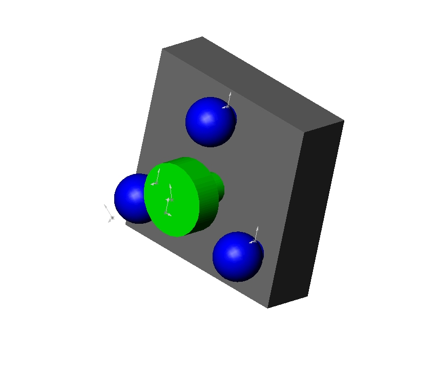
Two special parts were required for this prototype. The
first was a Samarium Cobalt magnet, which is used to hold the Wonder Wyler unit
to the robot. The magnet was obtained from McMaster-Carr as part number
5716K67 at cost of US$22.86 each. Dimensions for the magnet are 0.75 inch
diameter and 0.285 inch thickness, which allows the magnet to hold a maximum
force of 8 lbs. The McMaster catalog page can be found here: mcmaster_magnet.pdf.
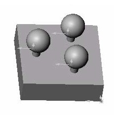
The second special parts were half inch diameter tooling balls,
dimensioned as slip fit These items consist of a sphere attached to a
small shaft, which are hardened to approximately a Rockwell C value of 60.
Critical dimensions are shown in the Solid Works drawings above and on the
McMaster catalog page. The tooling balls are McMaster part number 8484A13
and cost US$10.77 each. Three parts are needed per side plate. The
McMaster page can be found here: mcmaster_tooling_ball.pdf.
Manufacturing of Prototypes
Manufacturing of the side plate prototypes is rather
simple. The following simplified steps were taken:
-
Material cut to size along one direction (other direction
already to size as stock)
-
Material fixtured in milling machine and end surfaces are
milled to meet dimensions and smoothed
-
Material is refixtured and holes are located with center
drill
-
Outer holes are drilled through slightly undersized
-
Outer holes are reamed
-
Center hole is drilled out using 5/16 inch drill bit
-
Center holed is tapped with 3/8-16 tap to provide threads
-
Part is deburred and polished
-
Tooling balls are pressed into corresponding holes using
arbor press
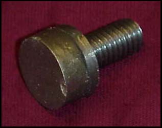
Manufacturing the threaded magnet unit was slightly more
complicated due to threading on lathe. The following simplified steps were
taken:
-
Fixture bar stock into lathe
-
Stock turned down to dimensions shown in drawings, including
threaded area, stress relief area, and magnet area
-
Add threads to part
-
Cut off part
-
Deburr part
-
Epoxy applied to magnet area and magnet is glued in place
Back