back to the main Axtrusion Page

The Modal Analysis of the Axtrusion

modalsetup.JPG (287423 bytes)

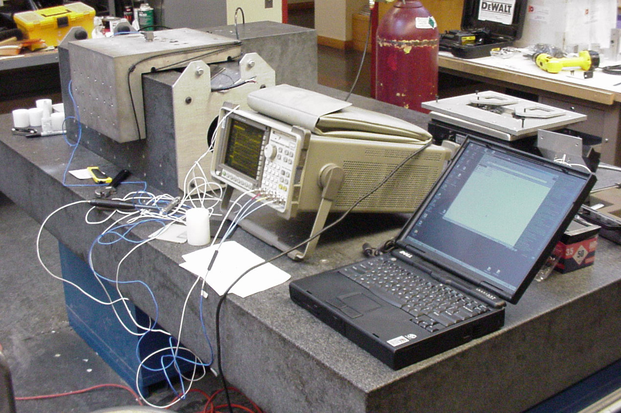
With the invaluble help of Ebberhard Bamberg I performed a modal analysis of the Axtrusion. We used a three (3) axis accelerometer connected to a Hewlett Packard 35670A Dynamic Signal Analyzer.

First the carriage was removed from the way and the accelerometer glued to the way.  This allowed us to find the modes of the way and table.  There were two dominate ones. One at 220 Hz and one at 332 Hz.

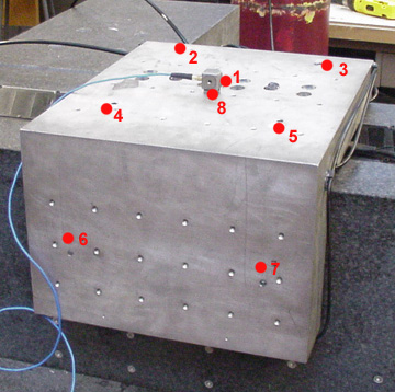
Then the carriage was put back on the way. Eight (8) points were diffined on the surface of the carriage. Point 1 was the impact point.  Points 2- through 8 were the measurement points.  The accelerometer was glued to each of these points in turn, and data collected for both the floating and not floating configurations of the carriage.

axtru_modal_points.JPG (66045 bytes)

The carriage and the 8 points used for modal analysis. Point 1 is the impact point, and Points 2-7 are the measurement points.

After the data was collected it was analysed in the ??? software by Star Linear. This allowed me to find the resonant frequencys of the carriage and it also shed of light on the some of the phycis and design considerations of the carriage.   Animations showing how the seven (7) measurement points moved with time were generated by the Star Linear software. Three of the more interesting modes are shown below.

modes607hz.gif (29131 bytes) This mode at 607 Hz is for when the carriage is floating. It had a magnitude of 38 and a damping percent of 3.3%

Notice the following:

Eventhough the excitations are completely vertical (Z axis), the carraige responces by oscilating in the direction of the preload.

The carriage flexes in a "hinging" motion

And the center of the top face appears to vibrate more than the resto the carriage.

modes362hz.gif (29802 bytes) This mode at 362 Hz is also for when the carriage is floating.  It as a magniture of 42 and a damping percent of 3.8%

Notice that the front left corner of the top surface of the carriage is oscilating more then the other three corners.   This is an indication that the bearing in this corner is not as stiff as the other three. This could be becuase the motor coil is slightly out of alignment with the carriage and/or magnet track and therefore preloading it less then the other bearings.  Or it could be becuase the top left front bearing is recessed ever so slightly more than the other three top bearings.  This would increase the air gap and also cause a reduction in stiffness.

modes1400hz.gif (39261 bytes) This mode at 1430 Hz is for when the carriage is NOT floating.  It has a magnitude of 300, and a damping percent of 0.6%

Notice the large oscillations of the center of the top face of the carriage with respect to the rest of the carriage.   This indicate that the center of the top face of the carriage would not be a good place to put precision equipment.

The data on all the significant modes found.

Freq [Hz] Damping [%] Magnitude [Output/Input] Comments

Carriage Floating

607 3.3 32.8 Main carriage mode with center oscillating in z.
362 3.8 48.11 Left front top air bearings moving the most.
487 1.9 5.5 Deformation of carriage spreading “hinge”
491 0.1 0.007 Carriage rocks back and forth, pure air bearings.

Carriage Not Floating

1430 0.6 300 Top center of carriage oscillating the most. The left side bearing oscillating much less.
501 1.3 2.3 Whole carriage moves up and down in the Z direction.