The Wonder Wyler project was proposed to MIT on September 1, 2000 at the conclusion of the ABB Robotics - MIT collaboration meeting. The original proposal was for Patrick Willoughby at MIT to quickly create a kinematic coupling to connect the new Wonder Wyler unit to the flange of the robot. However, this proposal was expanded to a more involved design as the complexity of the problem became more apparent. The design was to be supervised by Alec Robertson at ABB and Professor Alexander Slocum at MIT.
The Wonder Wyler Unit is a new product to be released by ABB Robotics as part of the Absolute Accuracy Package with the purpose of providing a quick, accurate, and movable measurement device for calibration of their line of robots. The device consists of two inclinometers placed perpendicularly to each other in the corner of a cube. When placed onto a measurement location on the robot, the inclinometers in the Wonder Wyler indicate the relative angles of a robot axis with respect to the ground. Using this data, the robot axes can be rotated so that the robot is calibrated to a specified zero position. This proposal was summarized by Alec Robertson in the following PowerPoint presentation: Absolute Accuracy Presentation. Preliminary CAD drawings were also provided: WonderWyler Detail.pdf. Initial wishes and concerns for the design were:
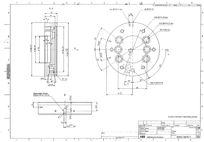
Initial design for the coupling was to proceed using information about the IRB 6400 model robot. Several data files were provided describing this robot:
| 6400R Brochure.pdf | |
| 6400R Product Manual.pdf | |
| 6400_flange.jpg | |
| loads_flange.xls. |
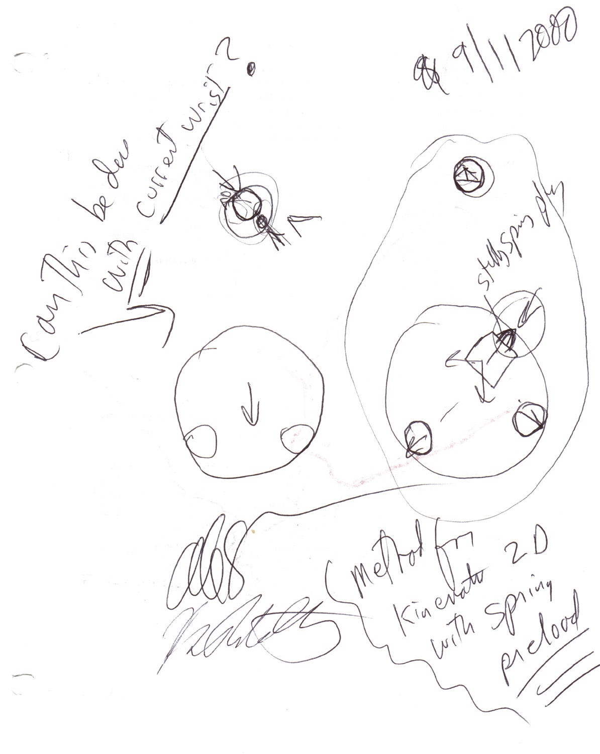
After the initial meeting, Prof. Slocum suggested a new coupling method that would allow the Wonder Wyler unit to connect easily to the flange. The initial design, shown in the original image initial_sketch.jpg, consisted of two pins that would rest against the inner recess of the flange, a pin that would rest inside the control pin hole, and a spring plunger that would provide a locking preload force. The design for the Wonder Wyler proceeded along these lines in the creation of a Excel spreadsheet that solves the force equilibrium equations and determines the contact stress. A wooden model of the three pin coupling was created at the MIT Hobby Shop by Patrick Willoughby in order to quickly verify that the coupling method would be successful. To reduce the size of the design, the spring plunger was removed from the design and replaced by a fourth "spring" pin. This pin would also rest inside the control pin hole on the flange and would provide the preload force by bending the pin. Using basic beam theory, the pin deflection could be translated into the preload force, which was added to the Excel spreadsheet.
At this time, ABB removed the requirement of a fixed flange design as the customers believed that the importance of an accurate measurement system was more relevant than keeping the original flange design. Because of this change, an additional design direction was added. This direction involved adding the standard groove pattern to the flange, without interfering with the tool attachment. Several different implementations were discussed, while the two most promising were the "ping pong paddle" arm design and the insert plate design. The paddle arm design consisted of the current flange design with an arm extended off the side to hold the coupling grooves. As an added benefit, this design could either be incorporated into the permanent flange design or be added later as an adapter kit. The adapter kit would use the three pin coupling to attach to the flange face with through holes for securing bolts. This idea had to be rejected as the paddle arm would interfere with existing wrist geometry during axis 5 rotation and the three pin coupling for the adapter kit could not withstand the emergency stop loading conditions. The paddle arm design could still be successfully incorporated into a robot which does not have the same physical wrist structure as the IRB 6400. Preliminary pictures of this design including CAD files are available as follows:
| View Files for Initial Ping Pong Paddle Arm Design | |
| View Files for Front Attachment Version of Paddle Arm Interface Plate | |
| View Files for Rear Attachment Version of Paddle Arm Interface Plate |
Therefore, the main design to be considered consists of a grooved insert plate which is placed in the recess of the flange. The grooves mate with balls on the side of the Wonder Wyler unit and are held together using a magnet. For future releases of the flange, these features could be incorporated in the design to eliminate the need for an insert plate. This incorporation could also lead to the use of the grooves as an alignment feature for the tool, which could help to improve the Absolute Accuracy program and provide ABB with a industry unique tool coupling interface. Further details relating to the insert plate are described in the Final Design section. Some different methods for securing the Wonder Wyler unit to the insert plate were considered, including electromagnets and a physical "coat hook" style device. It was decided that a single standard magnet placed on a threaded post would be the most cost effective and capable design. Patent 4,574,625 should be referenced regarding usage of the magnet. A copy of the patent is available here: Magnetic_coupling_patent.pdf. Alec Robertson updated his earlier presentation to include the coat hook idea and several other developments. This presentation is available here: Absolute Accuracy Presentation 2. In addition, an updated 3D model of the Wonder Wyler unit was created: picture 1 and picture 2. To verify the safety of the coupling, the geometry and forces were inserted into Prof. Slocum's kinematic coupling spreadsheet to determine if the coupling contact stress levels are satisfactory. As shown in the spreadsheet, the contact stress is approximately half of the critical value.
The final area for the Wonder Wyler unit to be investigated at MIT is the dynamic measurement for axis 1 calibration. This measurement requires that the Wonder Wyler unit be on the fixed base and the rotating axis 1 section. To do so, two grooves are located on the fixed outer edge and one groove is located on the inner rotating edge. The grooves are placed so that the entire assembly can rotate a total of approximately 2 degrees in either direction. ABB's measurement only requires a capability of 1 degree, so there is approximately 1 degree of freeness before the magnet contacts a groove. This extra spacing is crucial as contact between the magnet and groove creates an alternate coupling setup, which will no longer be accurate or repeatable for the measurement purposes.