 |
Solid Works CAD file and drawing |
 |
IGES File for part |
 |
PDF version of drawing |
The final design for the insert plate remains the same. Some alignment feature is necessary to prevent the insert from rotating inside the flange recess. A pin could be added to either the flange or insert that mates in a hole on the opposing part. The insert plate could also be incorporated into the design of the flange plate.
|
|
Solid Works CAD file and drawing |
|
|
IGES File for part |
|
|
PDF version of drawing |
This revision of the interface plate includes a small tab that mates with the existing bolt holes in the flange.
 insert_plate_tab.JPG |
Picture showing the new interface plate with alignment tab on lower left side of plate. |
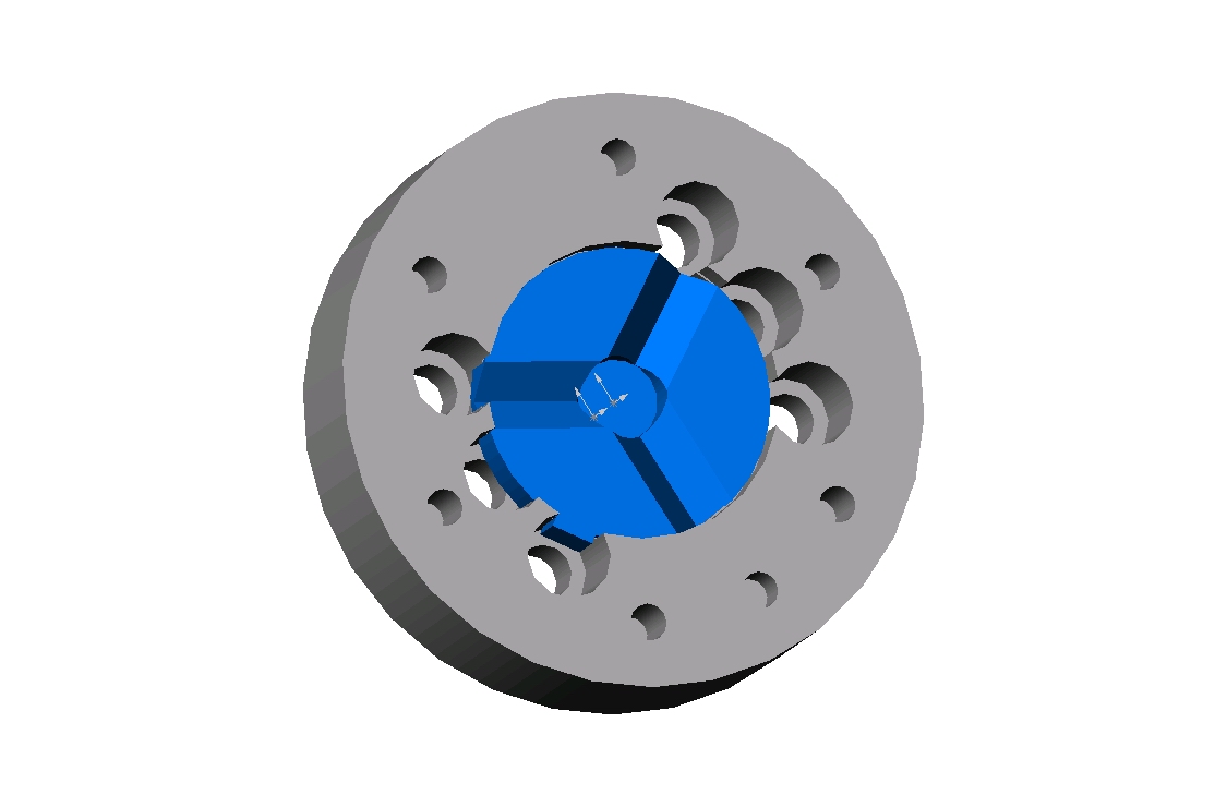 tab_plate_grooves.JPG |
Picture shows the new interface plate in the flange with the alignment tab in position. |
|
|
Solid Works CAD file and drawing |
|
|
IGES File for part |
|
|
PDF version of drawing |
Wonder Wyler Side Plate design is essentially the same as the prototype. The threaded hole specification has been changed to a similar metric thread.
|
|
Solid Works CAD file and drawing |
|
|
IGES File for part |
|
|
PDF version of drawing |
Threaded magnet unit design is essentially the same as the prototype. The thread specification has been changed to a similar metric thread.
|
|
Solid Works CAD file and drawing |
|
|
IGES File for part |
|
|
PDF version of drawing |
Groove on a post design is essentially the same as the prototype. Some dimensions were changed slightly.
|
|
Solid Works CAD file and drawing |
|
|
IGES File for part |
|
|
PDF version of drawing |
The drill template is a flat part with hole pattern required for setting up the grooves. Template could be used as an installation plate which could be fixed to the robot with grooves in it or be used as a template for drilling holes.
|
|
Solid Works CAD file and drawing |
|
|
IGES File for part |
|
|
PDF version of drawing |
Alternate groove design consists of a slightly longer groove. Instead of a post and hole, the groove has two holes. The holes would match to two pins on the robot.
|
|
Solid Works CAD file and drawing |
|
|
IGES File for part |
|
|
PDF version of drawing |
The drill template is a flat part with hole pattern required for setting up the grooves. Template could be used as an installation plate which could be fixed to the robot with grooves in it or be used as a template for drilling holes. This template has holes matching the alternate groove holes.
|
|
Solid Works CAD file and drawing |
|
|
IGES File for part |
|
|
PDF version of drawing |