Three Pin Kinematic Coupling Design
Design Overview
After the initial meeting with ABB, Prof. Slocum suggested a new
coupling method that would allow the Wonder Wyler unit to connect easily to the
flange. The initial design, shown in the original image
initial_sketch.jpg,
consisted of two pins that would rest against the inner recess of the flange, a
pin that would rest inside the control pin hole, and a spring plunger that would
provide a locking preload force. The design for the Wonder Wyler proceeded
along these lines until restrictions on flange design were removed by ABB.
However, development of this design was continued as the new coupling method
could still be used as an alternate design. Furthermore, it appeared that
the three pin coupling could be successfully applied on ABB - MIT projects
involving the IRB 6400 wrist and base as well as elsewhere in
industry.
Several different conceptual sketches and CAD models were
created to visualize the concept to ABB. At the same time, a detailed
mathematical analysis was under development in the form of MathCAD and Excel
documents. These documents solve the force equilibrium equations and
determines the contact stress for a set of coupling parameters. The
finalized version of the analysis were combined with instructions and images in
an Excel spreadsheet available below.
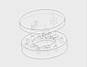
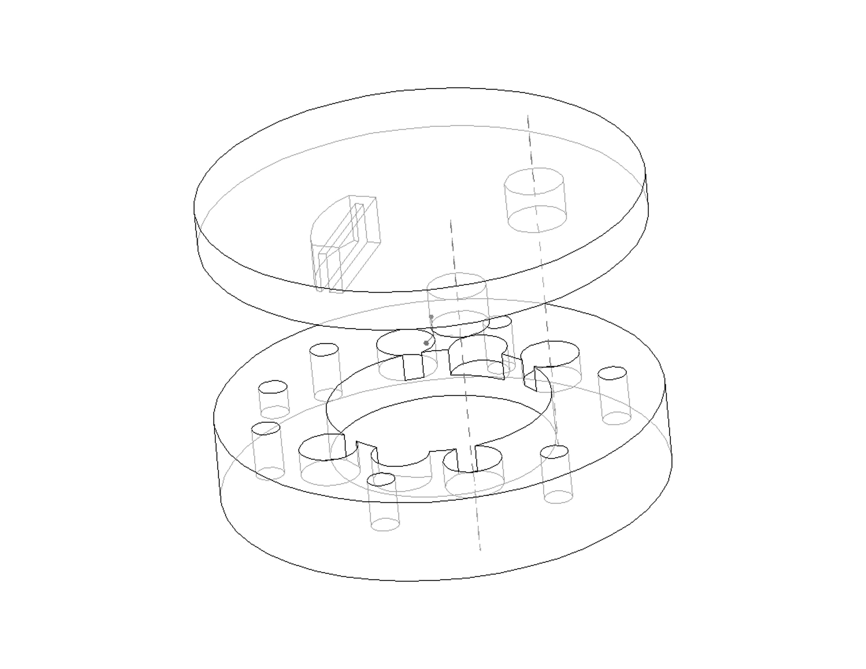
block_n_flange_bw.JPG |
Early CAD design concept |
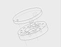
pin_n_flange_bw.JPG |
Early CAD design concept |

spring_plunger_concept.ppt |
PowerPoint file
describing the basic operation of the early conceptualization of the
three point coupling. This idea was to use the three pins with a
spring plunger providing the force. However, preliminary designs
using the plunger required a large block on the interface plate to hold
it, so this idea was used only as a development point. |

fbd_spring.jpg |
Free body diagram that accompanies the Excel spreadsheet. |

master_spring_solver.xls |
Final version of Excel spreadsheet for determining coupling and geometry parameters. |
To assist the conceptualization and verify the usefulness of the
coupling, a wooden model of the three pin coupling was created at the MIT Hobby
Shop by Patrick Willoughby. Pictures of this model are shown below.
The simple design involves several crude posts pressed into a block of wood as
an interface plate and two holes drilled into a separate piece as the robot
flange. The wooden flange also has a threaded hole to hold the spring
plunger. When placed on the posts, the coupling works extremely well with
loose tolerances during manufacturing.
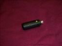
spring_plunger.jpg |
Spring plunger capable of providing 8lbs of force. Similar
plungers can be obtained from McMaster-Carr. |
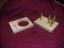
wooden_prototype_1.jpg |
Picture shows the components of the wooden three pin coupling. |
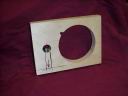
wooden_flang.jpg |
Picture shows the equivalent of the robot flange for the wooden
prototype. Note the lines drawn on the lower left side of the
part. These lines show where the spring plunger is threaded into
the wood. The small indentation on the larger circle is an
additional location for a spring plunger to provide an outwards force
from the circle's center. |
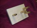
wooden_plate.jpg |
This part is the equivalent of the interface plate. The humorous
looking posts are brass rod which were fatigued to taper the ends.
The fourth post in the center of the block allows for additional spring
plungers to be used. |
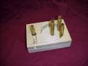
wooden_coupling_1.jpg |
This picture shows the engaged wooden coupling. |

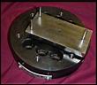
wooden_coupling_2.jpg |
This picture shows the engaged wooden coupling from above. |
As the design proceeded, it became apparent that the spring
plunger design would occupy too much space on the interface plate. To reduce the
size of the design, the spring plunger was removed from the design and replaced
by the fourth "spring" pin. This pin would also rest inside the
control pin hole on the flange and would provide the preload force by bending
the pin. Using basic beam theory, the pin deflection could be translated
into the preload force, which was added to the Excel spreadsheet. Using
sample dimensions, a basic prototype design was created. This prototype is
shown below. The length of each pin for the prototype was increased by 6mm
to facilitate testing. Proposed testing involves placing the interface
plate pins into the flange, but having the interface plate rest on 6mm diameter
balls rather than directly to the flange. By placing this space between
the two surfaces, the coupling could be loaded laterally to test the coupling
stiffness and verify the spreadsheet. When manufacturing the plate,
dimensions were determined without considering the bending stress in the
pin. After the coupling was attempted, it was apparent that the design was
not suitable as the spring pin bent. Suitable drawings and information are
included here to allow ABB to manufacture a working version of the
prototype. The deformation of the pin will be considered by MIT, as it may
become as useful version of the design. Similar to a quasi-kinematic
coupling, the deformation would create a unique repeatable coupling to the
specific flange. However, the extreme force required to couple the
prototype would not be acceptable.

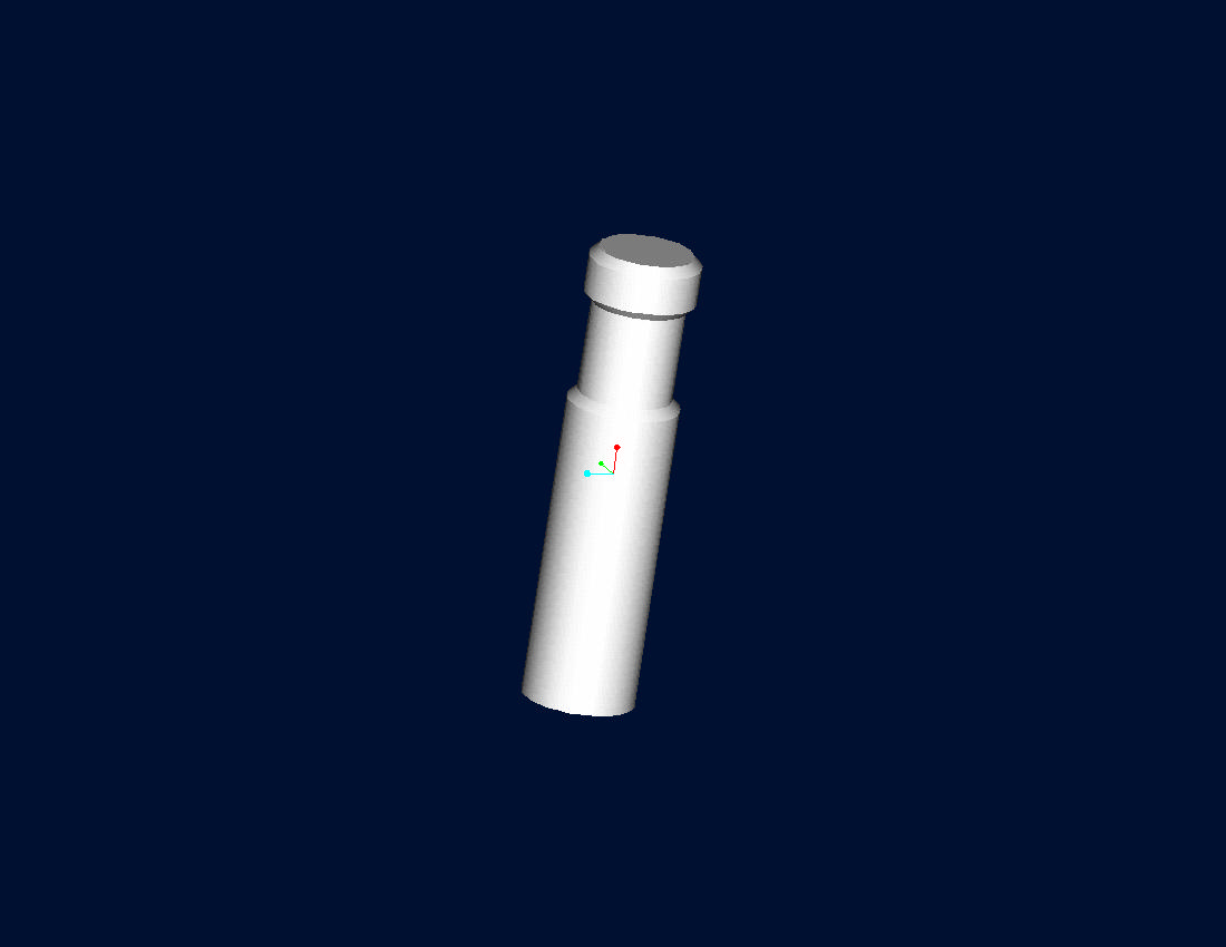
pin.jpg |
Initial concept model of the spring pin by Prof. Slocum.
Although it is not visible in the drawing, the small tab at the top of
the pin has a radius along the pin's length. This radius decreases
the contact stress at the interface. |
|
|
This PowerPoint file, three_pin_coupling_operation.ppt,
explains the three pin coupling as used on the current prototype.
This coupling consists of three pins for location and a fourth
"spring" pin which provides the preload force. |
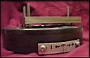
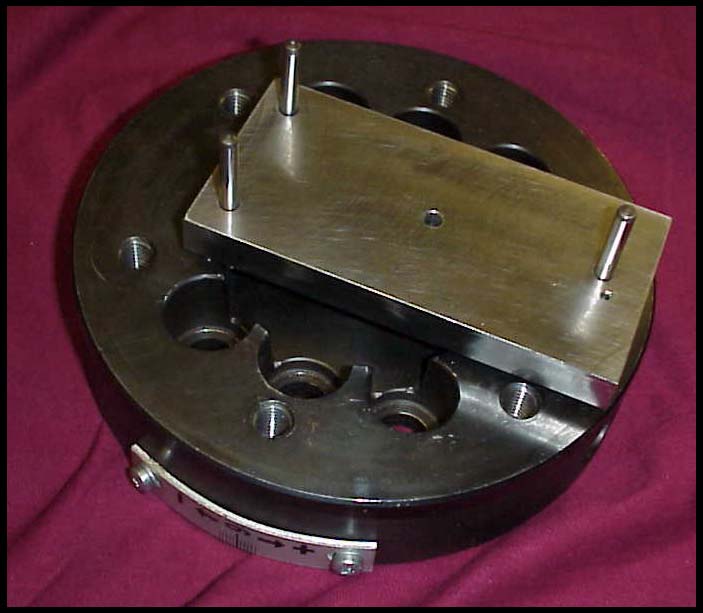
three_pin_unit_on_flange.jpg |
This picture shows the prototype of
the three pin coupling engaged with the flange. |
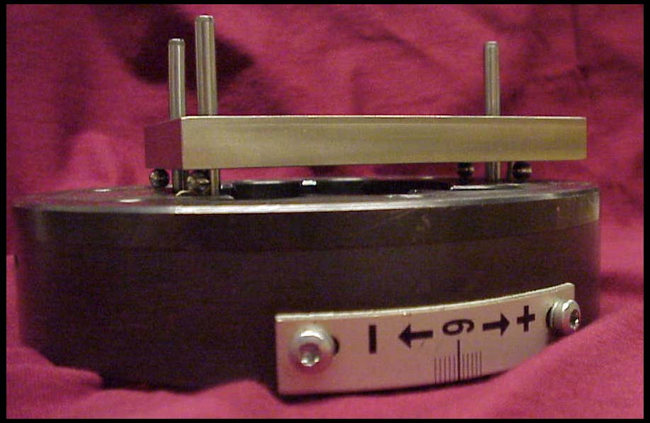
three_pin_unit_on_flange_side.jpg |
Side view of engaged three pin
coupling. |
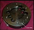
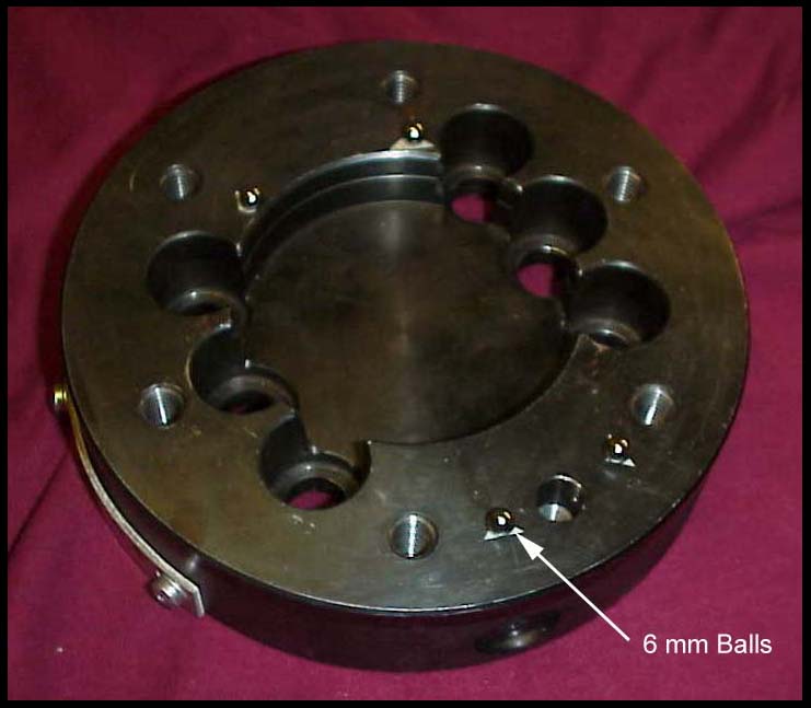
flange_plate.jpg |
Shows flange plate with 6 mm balls
to keep a small space between the two pieces without restricting motion in the plane of
the flange face. |
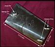
three_pin_plate_1.jpg |
Basic dimensions for three pin
coupling plate. Pins were purchased from McMaster with a diameter of 2 mm for the
spring pin and 5 mm for all other pins. Due to the length of these pins, a small
amount of the larger pins protrudes from the reverse side of the coupling plate.
This would not be present in a final design. The prototype design required a
significant force to create the coupling, which caused the spring pin to become bent. |
Drawings and CAD Files

 |
Solid Works 2000 CAD or IGES file of interface plate |
|
|
Tolerance analysis of interface plate using Solid Works 2000 |
 |
Drawings of interface plate in Solid Works 2000 and pdf |
Description of Special Parts
The special parts required for this prototype are hardened steel
dowel pins, which are available from McMaster-Carr. Two sizes were
ordered: 2mm and 5mm diameters. The 2mm diameter pins are part number
91595A203 and are US$16.71 for a package of 100 while the 5mm diameter pins are
part number 91595A424 and are US$35 for a package of 100 pins. The
McMaster catalog page is here: mcmaster_pins.pdf.
Manufacturing of Prototype
Manufacturing the prototypes was rather simple. The
following simplified steps were taken:
-
Material cut to size
-
Material fixtured in milling machine and all six surfaces
are milled to meet dimensions and smoothed
-
Material is refixtured and holes are located with center
drill
-
Holes are drilled through slightly undersized
-
Holes are reamed
-
Part is deburred and polished
-
Pins are pressed into corresponding holes using arbor press
New Design Files
The following files detail the new design of the three pin
interface plate to be manufactured at ABB for demonstration and testing.
|
|
Solid Works 2000 CAD or IGES file of interface plate |
|
|
Drawings of interface plate in Solid Works 2000 and pdf |
Back


