Chapter 4
Medium Scale Design Case Study: Wrist Interface
4.1 Background and Problem Description
4.1.1 Background
Out of the entire line of ABB Robots, the IRB 6400R robot is one of the most versatile and popular robots, especially in the automotive industry. Common uses include painting, assembly, welding, material handling, and other industrial tasks. With full six degree of freedom control, the 6400R is capable of positioning and orienting a 200 kg tool at a maximum speed of 2 to 3 meters per second.
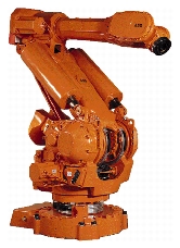
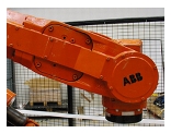
Figure 4.1 ABB IRB 6400R Robot Figure 4.2 Wrist Unit of IRB 6400R
While carrying a 150 kg load, the IRB 6400R can maintain 1 mm accuracy along the path while traveling at 1 m/s or 0.1 mm point to point accuracy. To achieve this level of accuracy, each robot is calibrated before it leaves the factory. The optimum calibration is performed by measuring a complete set of robot poses using a Leica LTD500 Laser Tracker System, a 3D tracking interferometer. These measurements are then used to develop a set of error parameters to describe the errors between the measured locations and the locations predicted from the robot's kinematic model. By integrating these parameters in the robot's control system, the position and orientation errors can be actively corrected for a given tool load.
Over time, the errors present in the robot system may decrease due to a noticeable change in robot performance or the replacement of a critical structural component. Down time of several hours of maintenance would be required to perform additional calibration necessary to restore the robot to optimal performance. In many industries, down time of several hours can shut down an entire assembly line, entailing many thousands of dollars of lost work. Often, some manufacturers will remove an entire robot rather than replace the major component online and recalibrate.
One of the more commonly replaced components on a robot is the robot wrist, which is a large component housing the motors and mountings for the last two axes. A wrist replacement can require approximately a half hour to perform the physical operations, while the subsequent calibration requires approximately two to eight hours to restore the robot to reasonable accuracy. To reduce the required calibration time, kinematic couplings could be incorporated in the interface between the robot wrist and the upper arm of the main structure. Since the coupling will be inherently more repeatable, the location of robot's tool flange will deviate less from the pre-replacement location. Instead of performing a lengthy calibration of a hundred or more poses, a much shorter calibration can be performed to restore the robot's accurate performance. For a full description of the repeatability and accuracy of a coupling, the effects of both repeatability and interchangeability must be addressed. The issue of interchangeability between wrist individuals is essentially an issue of tolerances and manufacturing and will not be discussed in this study.
4.1.2 Problem Description and Functional Requirements
Although kinematic couplings are used regularly in many precision engineering application, they have rarely, if ever, been applied to industrial robotics. For kinematic couplings to work in this setting, a new range of issues must be addressed including high loads, installation issues, and applicability. To develop experience with these issues, several kinematic coupling designs will be created for the IRB 6400R robot to introduce the concepts for future implementation in ABB robots. The end product of this work is to develop experience using kinematic couplings in industrial robotics and to transfer this experience to the engineers at ABB. Design of the 6400R couplings is guided by the following functional requirements:
- Improve the repeatability of a wrist replacement on the 6400R robot.
- Minimize physical changes to wrist structure.
- Minimize or prevent any reduction in structural performance of wrist interface.
- Minimize cost of new wrist design.
Initially, the goal of the new interface design was to reduce the existing wrist replacement error of 1.0 mm. During testing, a single wrist interface revealed that replacement repeatability of 0.1 mm could be achieved with the existing interface. However, this repeatability may not be indicative of the performance of all wrist interfaces, as only a single interface was measured. Since these measurements may indicate that the wrist interface performs much better than originally speculated, the target for design repeatability was to render the replacement of a wrist indistinguishable to the measuring system. The Leica interferometer system that is currently used for calibrations at ABB is capable of measuring 10 mm per meter, which translates to a measurement accuracy and design target of about 20 to 30 mm.
4.2 Design Development and Construction
The strategy for achieving these goals is to implement a series of adapter plates that could be fixed to the existing wrist interfaces and that allow the new couplings to be safely tested. The new interfaces to be attempted are the standard kinematic coupling using canoe ball elements and a three pin coupling. Quasi-kinematic couplings were not implemented and tested due to time and financial constraints.
4.2.1 Existing Wrist Coupling
As shown in Figure 4.3 and Figure 4.4, the existing wrist coupling consists of rather complex implementation of a pin coupling.
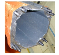
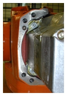
Figure 4.3 Existing Coupling Features on Arm Figure 4.4 Existing Coupling Features on Wrist
Primary coupling features include four highly tolerances control tabs on the robot structure that interface with similarly toleranced control surfaces on the wrist. While the control features constrain two translational degrees of freedom in the interface plane, an additional control pin is required to constrain the third degree. Surface contact across the interface plane constrains the remaining degrees of freedom. Across the interface, forces and moments are opposed using eight bolts normal to the interface and friction coplanar to the interface. As extremely high loads are carried by the interface, friction between the interface surfaces is not sufficient to support the moments so additional dimpled friction plates are included at the interface, as shown in Figure 4.5.
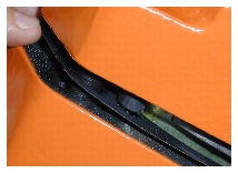
Figure 4.5 Friction Plate at Wrist Interface
X - Force (kN) -13.7, 3.0 -13.4, 28.4 Y - Force (kN) -12.9, 9.8 -23.7, 29.9 Z - Force (kN) -12.8, 13.1 -30.6, 28.1 X - Moment (kN-m) -2.8, 5.4 -14.1, 8.6 Y - Moment (kN-m) -8.7, 5.7 -8.2, 20.4 Z - Moment (kN-m) -9.5, 7.4 -31.2, 29.3 Table 4.1 lists the forces and moments on the interface for the normal operation and emergency braking conditions as predicted by simulations. The minimum and maximum values given are for the worst possible conditions in the specified direction and would never occur simultaneously.
As mentioned above, the repeatability of an existing wrist replacement is estimated by ABB to be 1 mm at the tool flange, while the measured repeatability of a wrist individual is 0.1 mm. Due to the nature of the coupling, both interchangeability and repeatability are limited by the tolerances of the interface geometry, which are approximately ±0.010 to ±0.100 mm. The application of kinematic principles will decrease the dependence of repeatability on tolerances.
4.2.2 Kinematic Coupling
The first of the two new coupling interfaces is the standard kinematic coupling. Because of the high loading case occurring at the wrist, canoe ball elements will be used to improve performance. The canoe balls used on the wrist were originally designed for a separate project and ordered in bulk to reduce the price.
Figure 4.6 Canoe Ball and Groove Elements
Consequently, some limitations are placed on the design, although their load capacity is sufficient for the wrist. Basic material properties for the canoe balls are 420 Stainless steel and hardened to 50 - 55 Rockwell C with surface finish as ground. Basic dimensions are radius of 250 mm for the canoe surfaces and an equivalent ball diameter (contact point to contact point) of 30 mm.
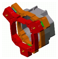
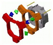
Figure 4.7 Wrist Interface Assembly Figure 4.8 Exploded Wrist Interface Assembly
In Figure 4.7 and Figure 4.8, an assembled model and an exploded model of the CAD geometry are shown. The components are ordered from left to right as follows: interface plate to wrist, groove elements, canoe ball elements, interface plate to arm, arm interface, and preload bolts. Interface plates are made of 17-4 ph Stainless Steels, which are relatively easy to machine while providing high strength, high hardness, and excellent corrosion resistance.
General Design Concerns
Because of the restricted space available on the wrist interface, placement of the coupling becomes a major problem to overcome. For the prototype design, this problem is bypassed by creating extra tabs that protrude from the wrist interface area. These tabs were sized quite large to prevent any bending of the interface plates during testing and operation. In future revisions of this design, the canoe balls could be incorporated as integral features to the wrist interface, especially since large protrusions from the wrist are undesirable in any environment. Furthermore, the gap between the two interface plates must be sealed for use in any industrial environment where grease, oil, debris, and other contaminants could be introduced to the internals of the robot arm. Some form of interface seal or a quasi-kinematic coupling could be used.
One concern for using interface plates to test the coupling prototypes is the possibility of relative motion between the components. If relative motion of one plate to the robot structure were to occur, repeatable results would be impossible to obtain. To prevent undesired motion, each interface plate will be secured to the corresponding robot interface with four M12 bolts. Four additional M12 bolts will be placed through the entire assembly as an emergency security precaution against wrist damage if the preload bolts or interface plates fail.
Similarly, relative motion between the coupling elements and the interface plates is undesirable. To prevent motion, the coupling elements are press fit into corresponding holes on the interface plates. Rotation about the element shank is prevented using a press fit dowel pin with a matching hole on the element.
Preload
Preload for the kinematic couplings was determined based on the weight of the wrist only, assuming the wrist is hanging from the arm at a 45° angle with respect to ground. Normal operation forces and emergency stop forces were not considered, as ABB engineers limited testing of the wrist prototypes to a static replacement to prevent the chance that the robot might be damaged. Based on an estimate of wrist mass of 100 kg, it was determined that 10 kN of preload through each ball center was necessary to set the coupling. Because of the small size of the coupling elements, the maximum size bolt is limited to an M6. Using the procedures documented in Bickford and Nassar, this preload translates to a required 15 N-m torque on a class 12-9, M6 bolt, which ensures that stress in the bolt remain 90% of the yield stress. No additional preload can be applied on these coupling elements using these bolts without risking bolt failure.
Contact Stress
Under the preload and weight of the wrist, the kinematic couplings exhibit contact stress at an acceptable level of less than 40% of the allowable stress. Contact stresses increase only slightly if the normal operation forces are applied to the coupling elements; however, emergency braking loads will cause high contact stresses and reversal of contact forces. The mathematics describing performance of this coupling are included in Appendix A.
Stiffness
Since one of the main functional requirements is to minimize any reduction in performance of the new wrist interface, joint stiffness must be investigated. To perform a relative comparison of stiffness, a series of finite element models were created using the SDRC IDEAS software package. Results of simulations for four models are shown in Table 4.2.
For each model, two separate simulations were performed to analyze the stiffness variance in different directions. Results indicate the deflection resulting from a 1000N force in either the Y or Z direction as shown in the corresponding model figures below. First, two simulations were performed to determine the stiffness properties of the arm geometry as if it were a straight beam and with the existing interface. Relatively similar deflections occurred in both the Y and Z directions for both models, indicating that the bolted interface performs almost like a single, contiguous piece.
In order to accurately describe the stiffness of the canoe ball interface, two simulations were performed with separate approximations of the interactions between the canoe ball and groove elements.
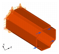
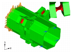
Figure 4.9 FEA Model for Straight Beam Figure 4.10 FEA Model for FEA Approximation
The first approximation uses hinge flexures to simulate the stiffness of the new interface as predicted by the Hertzian contact mechanics in Appendix A. In Figure 4.10, the flexure geometry is determined to be a 35 mm cube with cutout radius of 17.5 mm. Instead of geometrically changing the stiffness properties, the second approximation applies an altered Young's modulus to a 35 mm cube to simulate the predicted stiffness change. In both approximations, each canoe ball - groove interface is replaced by one of the approximate geometries. Mathematics necessary to design the hinge flexures and the material change are included in Appendix C and FEA plots are presented in Appendix D. Overall, both approximations illustrate significant reductions in the stiffness of the interface from the original design. To fully understand the effect of the stiffness reductions, the changes must be incorporated into the robot kinematic and dynamic models to determine whether or not undesired performance will result.
4.2.3 Three Pin Coupling
The second coupling to be tested on the wrist interface is the three pin coupling, a form of the planar kinematic coupling. Similar to the design of the three pin flange interface in Chapter 3, the three pin wrist interface uses three pins with a properly applied preload to constrain the three degrees of freedom in the interface plane and surface contact to constrain the remaining degrees.
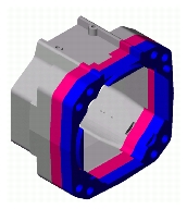
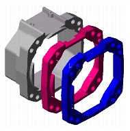
Figure 4.11 Three Pin Wrist Assembly< Figure 4.12 Exploded Three Pin Wrist Assembly
General Design Concerns
One of the benefits of using the three pin coupling on the wrist is the ease with which the existing wrist coupling geometry can be adapted into the more deterministic design. The existing coupling consists of a control pin and four cylindrical control surfaces that are coradial and concentric. By removing two of the control surfaces, all necessary features are present for the positive coupling half. On the mating interface, the control recesses corresponding to the remaining control surfaces can be machined out to create flat surfaces for line contacts with the two control surface pins. Due to the large radius of these control surface pins, they possess high load carrying capacity using the same phenomenon as the canoe ball elements. The final mating feature is a specially designed pill shaped hole that accepts the control pin and allows for a singular line contact along its circumference. Figure 4.13 shows a cut-away prototype of the two coupling interfaces to illustrate the general geometry. To check the design for success, a force and moment balance on the interface is performed using the free body diagram in Figure 4.14.
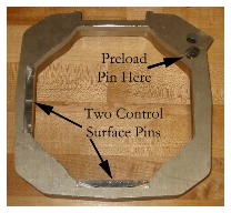
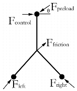
Figure 4.13 Basic Three Pin Geometry Figure 4.14 Free Body Diagram for Three Pin Preload
When using the three pin coupling, two separate preloads are required to properly set the coupling. The first preload occurs in the plane of the coupling and is used to set the coupling against the interface friction and any in-plane static loads. Since the coupling is only subjected to the weight of the wrist, the in-plane preload is not required to apply any constraining load against the wrist weight. In-plane preload is applied using a M6 set screw with a brass tip. By including the brass tip, some compliance is added to the preload bolt to prevent overconstraint. The exact in-plane preload force could not be calculated as the coefficient of friction for the interface was unavailable. For the second preload, bolts normal to the interface plane close the coupling and apply the load carrying preload. The weight of the wrist and small dynamic forces caused by small moving the robot to any measurement positions will be held four M12 bolts threaded into the robot structure.
Stiffness
One of the main benefits of the three pin coupling is that no reduction in stiffness occurs in comparison to the original coupling. On the existing interface, the only load carrying features are the perpendicular bolts, frictional plates, and surface area, all of which remain on the three pin coupling. The changes between the two couplings occur on control features that are used for alignment purposes only and have no structural properties. Estimates of three pin coupling stiffness would be similar to those for the bolted joint shown in Table 4.2.
4.3 Physical Prototypes
As mentioned previously, each wrist prototype consists of two interface plates made of 17-4 PH stainless steel. Negative features of the robot structure's interfaces are machined into the appropriate side of the coupling to easily allow installation of the plates. Four M12 bolts secure each of the plates to the respective robot structure. For the canoe ball and groove coupling, the coupling elements are press fit into blind holes and are pinned to prevent rotation about the shank. The three pin coupling has features as machined and requires no additional assembly. The prototypes are shown in Figure 4.15 and Figure 4.16 as single units attached to the robot and as coupled.
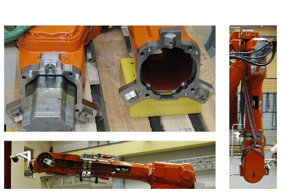
Figure 4.15 Canoe Ball and Groove Coupling Prototypes 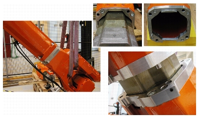
Figure 4.16 Three Pin Coupling Prototypes
Testing System and Procedure
The testing setup for the ABB IRB 6400R consists of a full robot cell, including robot, control system, and a Leica LTD Laster Tracker. To measure the effect of wrist replacement, a cat's eye retro-reflector was attached to the tool flange. The retro-reflector allows the laser tracker to follow the location of the robot while measuring the distance between the robot and laser head and the three angles of the laser head. In the Leica computer controls, these measurements are combined to present the X,Y,Z coordinates of the reflector with accuracy of 10 mm per meter. Corrections are made in the controller using a temperature measurement to correct thermal errors in the measurement system.
To measure the repeatability, each type of coupling was installed on the existing interfaces then coupled together with the robot powered down. Upon powering the robot, measurements were taken at five points throughout the robot's working space, as shown in Figure 4.17. This procedure is contrary to the initial assertion by ABB engineers that the robot could not be moved with the new couplings in place due to possible safety risks.
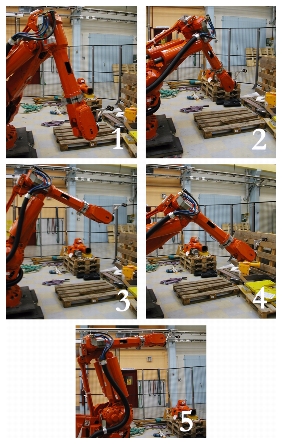
Figure 4.17 Fives Positions of Robot in Dynamic Test
However, measurements of the robot at different points in the workspace were very instructive on the performance of an under designed coupling. Note that in positions three and five, the angle of the wrist deviates significantly from the position where the arm is perpendicular to the ground. As the original design of the canoe ball and groove coupling was limited to this position only, optimal performance could not occur in these significantly different positions. Additional measurements were taken without moving the robot to assess the static repeatability of the coupling. Furthermore, two separate installation positions were tested to investigate the effect of the initial relative position of the couplings. The first position is the standard wrist replacement position used for the IRB 6400R, shown in Figure 4.18, while the second position places the arm and wrist parallel to gravity, shown in Figure 4.19.
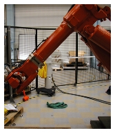
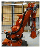
Figure 4.18 45° Installation Position Figure 4.19 90° Installation Position
In both positions, installation is assisted using a crane to grossly position the wrist. Fine positioning is performed by evenly tightening the peripheral bolts until the contact surfaces touch. Using stepped torquing of 10%, 50%, and 100%, the proper preloads are applied to the three preload bolts on the canoe ball and groove coupling. The peripheral bolts are tightened to finger tight to provide security against wrist separation if the preload bolts fail. Due to underestimation of the wrist weight and the presence of unexpected dynamic forces, extra preload was required to set the coupling in most positions. Two methods were employed to apply additional preload: loading applied through peripheral bolts in parallel with the preload bolts and clamps applied in series with the preload bolts. The lower left image in Figure 4.15 shows the clamps installed along the preload bolts.
For the installation of the three pin coupling, the peripheral bolts are tightened to still allow movement along the interface plane. The in-plane preload is then applied to set the coupling. During testing, a torque wrench was not available with the proper attachment for the in-plane preload bolt. Therefore, a repeatable in-plane preload was not possible for these experiments. The preload bolt was tightened until the coupling plates move into place, then the peripheral bolts are tightened to 120 N-m as typically performed during installation. After two wrist replacements, noticeable deformation of the brass tip on the preload bolt was observed and the bolt was exchanged every two wrist replacements. Friction plates are also placed on the interface during coupling for maximum load capacity. After the first series of measurements, some change occurred in the coupling, causing a significant decrease in the repeatability. It is surmised that damage occurred between the control pin and receptacle due to the creation of scratches and marks in the interface region. When exchanging the wrist in the 45° position, a large moment is incurred about the lifting straps. This moment creates motion between the wrist relative to the arm, causing the precision interface features to scrape each other and remove the deterministic relationship. Future testing and implementations should be performed in the 90° position to prevent damage.
4.3.1 Results
The easiest way to present the results is show the progression of measurement results to illustrate the changes caused by the different variables. Figure 4.20 shows a table of the different measurements of average point to point repeatability, progressing in an improved understanding of installation procedures. Table 4.3 shows the results with matching conditions for each measurement in Figure 4.20.
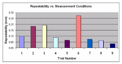
Figure 4.20 Average Repeatability vs. Measurement Conditions for Canoe Ball and Groove Coupling
Preload listed in the additional preload column is in addition to the 10 kN preload applied using the preload bolts. Numbers listed correspond to the preload torque applied to the peripheral bolts, while the word clamps indicates the unmeasured clamp load. In the fourth and fifth series of measurements, the increase in peripheral preload improved repeatability, however, the increase to 120 N-m in the sixth measurement created a sufficiently large bending moment to cause relative motion between the coupling elements. While adding preload in parallel with the preload bolts is undesirable due to the bending moments, the measurements with additional preload applied in series improved the repeatability without undesirable effects. Since the size of the preload bolts could not increase, the use of clamps increased the preload applied and improved repeatability. Clamps are not a desirable addition to the design of the robot, so future coupling designs require more flexibility in preload application. In addition to preload changes, noticeable improvements in repeatability coincided with improved bolting procedure and installation position. The main benefit of performing a wrist installation in the 90° position is that all forces on the coupling are parallel to the installation direction. Non-parallel forces induce rotations of the coupling, causing quite different initial positions of the elements and different force distributions across the elements.
For the three pin coupling, only three measurement sets were available due to the damage incurred. Figure 4.21 shows the average point to point repeatability results for the three pin coupling and Table 4.4 lists the conditions at each measurement.
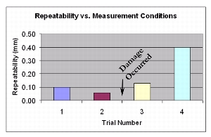
Figure 4.21 Average Repeatability vs. Measurement Conditions for Three Pin Coupling
As mentioned earlier, the first measurements of the three pin coupling indicated potential for a significant increase in repeatability with a minimal change in the design. However, damage occurred before sufficient measurements could be taken and repeatability of the coupling became worse than the existing coupling.