Chapter 3
Small Scale Design Case Study: The Calibration Cube
3.1 Background and Problem Description
3.1.1 Background (Robertson, 2001)
In the field of industrial robotics, many different calibration methods exist to help reduce error in the robot system. One of the most common calibration methods, locating the manipulator home position, requires that the robot be positioned with all joint angles specified to have a value of either zero or 90 degrees. For large industrial robots, this home position must be repeatable to within 0.2 mm in Cartesian space at the end point of the robot. Using robot kinematics, the Cartesian requirement can be transformed into a required joint angle repeatability of 0.01 degrees.
During a standard production run of ABB industrial robots, each robot undergoes several calibration procedures, including a complex procedure for finding the home position. Once the home position is found, specialized error parameters are formulated based on the robot kinematics and stored in the controller. These parameters are valid for the initial robot configuration, however, they may change over the lifetime of the manipulator, especially if components are exchanged. If the calibration process used during manufacturing could be improved and simplified, the robot could be recalibrated whenever necessary, without requiring the expensive and complicated measurement systems.
To improve the calibration of the home position, ABB engineers first wanted to simplify the method of calibration. The home position can be found using one of the following three separate methods of calibration:
- Relative calibration - Expensive process that requires each component in the robotic structure to be defined relative to the previous component. Accuracy from relative calibrations can vary based on the accuracy of the robot components.
- Optimal calibration - This process uses a measurement system combined with kinematic models of the robot to measure many positions of the robot and correct any errors present in structure. Accuracy from optimal calibrations can vary based on the robot positions and kinematic model.
- Leveling based calibration - Process uses simple electronic levels known as inclinometers to easily orient each component of the robot structure with respect to the angle read by the inclinometer.
Because leveling methods are much simpler and cost effective, leveling based calibration was chosen for the new device. However, several aspects of the design must be reconsidered to reasonably achieve the required repeatability. The overall precision of the new device combines the accuracy of the robot control system with the repeatability of the device structure and the interface between robot and device. A baseline home position repeatability can be estimated from the critical component of the robot control system, the resolver accuracy, which is typically on the order of 100 micrometers based on ISO standards for a defined speed and payload.
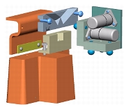
In order to test out the concept of a leveling system, ABB engineers developed a prototype unit using inclinometer sensors from the Wyler AG Zerotronic System. These sensors employ a digital capacitance system that measures the deflection of a small pendulum mounted between two electrodes. Originally, two sensors were mounted on separate right angle plates that were placed at several mounting points on the robot. One sensor was placed on the base of the robot to provide a reference angle for each of the subsequent measurements. To measure each joint, the second leveling sensor was placed at one of four locations on the robot. Each joint of the robot is then manually moved to a position that corresponds to the predefined angle. Testing of this initial system presented mean recalibration error of 1.0 mm measured at the tool interface of the robot. This error can be broken down to show that half of the error is a result of the mounting interface, a third is a result of the plate construction, and the remaining error is considered random.
To improve the initial device, the prototype was reduced to a single right angle plate with the two sensors mounted perpendicular to each other within the structure. Operation of the calibration procedure was also improved with automated software to adjust the position of the robot joints to match the values required by the sensor values.
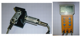
Figure 3.1 Wyler Sensors and Accompanying Meter
Figure 3.1 shows the resulting sensor unit along with the meter. With the new device, the unit was placed on the base to measure the reference values. The same unit is moved to four additional points on the robot, as shown in Figure 3.2, to measure the remaining joints.
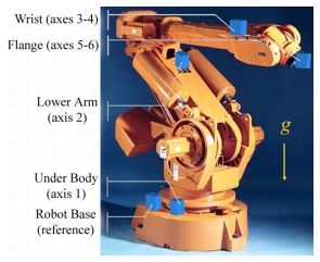
Figure 3.2 Location Point for Levelling Device on Robot
3.1.2 Problem Description and Function Requirements
At this point in the design process, the main component of the error budget to be addressed was the coupling interface between the sensor unit and the robot. Slocum and Willoughby become involved in the design of the device, known as the "Wonder Wyler", to assist with improvement of the coupling process. After some discussion, a set of initial functional requirements were developed:
- Reduce error in coupling of device to robot to allow for 0.05 degree accuracy at each joint.
- Unit should be compatible with several models of robots without requiring extensive change to the robot structure.
- No changes can be made to the interface on the tool flange, which has space limited to 50 mm by 50 mm on the smallest robot. ABB engineers require that an extra interface plate be placed between the sensor unit and the robot if the unit cannot attach directly to the flange.
- Coupling should be easily removable using simple preload application, but will not fall off. Mechanical connections are desired for extra security.
- Coupling should prevent improper installation.
During the course of the project, these requirements were changed frequently as ABB's customer needs were fine tuned. The final list of requirements were as follows:
- Reduce error in coupling of device to robot to allow for 0.05 degree accuracy at each joint.
- Coupling should be easily removable using simple preload application, but will not fall off.
- Unit should be compatible with several models of robots without requiring extensive change to the robot structure.
- Coupling should prevent improper installation.
3.2 Design Development
As the design progressed, the functional requirements coalesced into four major design tasks: coupling type, securing force, coupling location, and dynamic coupling. Each of the four tasks encompasses many design decisions for all of the functional requirements due to their highly coupled nature.
3.2.1 Coupling Type
Standard Ball and Groove Kinematic Coupling
The choice of coupling type for the interface is the most crucial design decision to affect the precision of the device. To design the coupling, the requirements of the coupling type were low load capacity, high repeatability, and medium cost. Since the device was small, standard ball and groove kinematic couplings could be used with out inducing high contact stresses. Physical construction of the coupling would consist of three balls aligned in the traditional triangular pattern placed onto a side plate of the unit with matching grooves placed on the desired measurement locations.
On the device side of the coupling, the inclinometer unit consists of three plates accurately mounted in an open cube structure, with three spheres placed on the outer surface of the bottom and front plates. Rather than machine balls into the surfaces, standard tooling balls were press fit into precisely located holes. The cost of the coupling could be significantly lowered by using the press fit balls, since tooling balls can be purchased fairly cheaply from a wide number of vendors with extremely good tolerances. In order to secure the unit, a minimum preload of 15 newtons was required to hold the approximately 1 kg unit in place. A factor of safety of 2 was applied to the design to ensure that the device would not fall off during any movements of the robot. Although the maximum forces on the interface are quite low, the standard kinematic coupling design was performed to verify that contact stresses were sufficiently low while the preload is successful at preventing the reversal of any contact forces. To prevent improper device installation, the angles between the grooves could be changed from the standard 120-120-120 degree setup by 5 degrees without significantly affecting the coupling stability. Figure 3.3 shows a CAD model of the design using half inch balls mounted in a 20 mm circle on a 50 mm by 50 mm plate of steel and Figure 3.4 shows the CAD concept of the sensor unit comprised of an open cube structure.
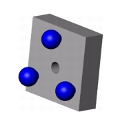
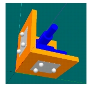
Figure 3.3 CAD Model of Side Plate Figure 3.4 CAD Model of Open Cube Structure
On the robot side of the coupling, it was necessary to create three grooves on five locations, represented by the blue squares shown in Figure 3.2 above. Initially, grooves were machined into separate plates that were bolted into existing bolt holes on the robot structure. After some preliminary testing, it was discovered that bolting additional groove plates on the robot did not have sufficient repeatability due to the inaccuracy of the bolting procedure. A simple cost versus accuracy analysis was performed showing that the cost of accurately mounting groove plates to the robot each time the device was used exceeded the cost of accurately machining or casting grooves into the robot structure. V-grooves with an angle of 90 degrees are used to optimize stability and for ease of manufacturing.
Flange Mounting and Three Pin Coupling
Before the ABB engineers had relaxed the requirement for placing grooves into the robot structure, several different design variations were developed to allow the "Wonder Wyler" unit to attach to the flange without requiring changes to its critical features. The tool flange, located at Flange (axes 5-6) in Figure 3.2 and shown close up in Figure 3.5, is the high load connection interface between tools and the robot.
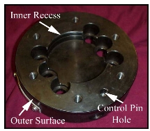
Figure 3.5 Flange Interface on ABB IRB6400 Robot
The design variations included a three pin coupling that interfaces with the toleranced features on the flange and several concepts for including coupling features on non-critical surfaces of the flange. In this section, only the three pin design will be discussed, while the latter designs will be presented in a following section.
After the initial project discussion with the ABB engineers, it was determined that a three pin coupling could work as an interface to an extra plate between the flange and the "Wonder Wyler" unit. Pins on one side of the plate would easily couple with the toleranced features on the flange (noted on Figure 3.5), while grooves on the reverse side would couple with the sensor unit. The initial design concept consisted of two pins resting against the inner recess of the flange, a pin that would rest inside the control pin hole, and a spring plunger that would provide a locking preload force. To model the interaction of the pins with the flange, a detailed mathematical model was developed to describe the forces acting in the system and is included in Appendix B. Concurrently, several basic wooden prototypes were constructed to visually assist the design of three pin coupling. Figure 3.6 shows the various components of the wooden model uncoupled, while Figure 3.7 shows the coupled model with the spring plunger direction indicated by the black arrow.
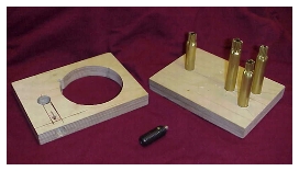
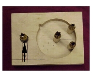
Figure 3.6 Components of Three Pin Model
Figure 3.7 Assembled Three Pin Model
In Figure 3.6, the left component represents the critical features of the flange, including the control pin hole and inner recess, as well as a side hole for insertion of the spring plunger. A spring plunger consists of a small, spring loaded pin with a round head placed inside a threaded casing, as shown in the center of the figure. For the three pin coupling, the spring plunger is used as an adjustable preload. The right component represents the three pin plate, with a fourth center pin used for additional adjustments.
As the design progressed, it became apparent that the spring plunger design would be unsatisfactory as the flange would require major modification to accept the plunger and the plunger would occupy too much space for the smaller robot designs. To reduce the size of the design, the spring plunger was removed from the design and replaced by an additional feature on the interface plate called the spring pin. This pin would also reside inside the control pin hole on the flange and would provide the preload force by resistance to the bending of the pin. In Figure 3.8, a possible design for the interface plate is shown using an asymmetric split pin, highlighted in the box. To create the preload force, the split pin is sized slightly smaller than the matching hole. The repeatability of the contact is ensured by placing the gap off center, which allows the larger section to remain rigid compared to the smaller section. The smaller section is sized to customize the preload. Due to the complicated machining requirements of this design, a simpler design was formulated as shown in Figure 3.9, using a straight dowel pin as the spring pin. The spring pin action is similar to a cotter pin, where two pins separated by a small gap are forced into a slightly smaller hole.
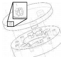
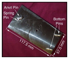
Figure 3.8 Asymmetric Split Pin Design Figure 3.9 Prototype of Three Pin Coupling with Spring Pin
As in the split pin design, one of the two pins has a diameter significantly smaller than the rigid contacting pin, called the anvil pin. Using beam theory, the pin deflection caused by the diameter reduction can be translated into the preload force with relatively simple calculations. These simple calculations are included in Appendix B. The prototype shown in Figure 3.9 is capable of producing a 20 Newton preload force when a deflection of 0.5 mm is enforced on the spring pin using the flange geometry.
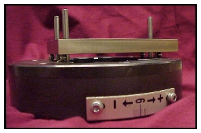
Figure 3.10 Three Pin Prototype Coupled with Flange
In Figure 3.10, the three pin coupling prototype is shown successfully coupled with the ABB IRB6400 robot flange. The small space between the interface plate and flange would normally be undesirable for a finished product as the design cannot be deterministically located along the flange plane. When designing the prototype, this space was included to allow future testing of three dimensional stiffness of the coupling with minimal interface friction. To reduce friction yet preserve some constraint, 6 mm diameter balls were placed between the plate and flange to allow the plate to move in the plane of the flange, but still be constrained for out of plane motion. A tolerance analysis was performed using a flexible CAD model in SolidWorks to show that repeatability of 0.05° is possible with tolerances of ±0.05 mm.
After the ABB engineers had relaxed the requirement that no changes be made to the structure of the flange, it was quickly determined that the best design would be to include grooves integral to the flange structure. The same groove pattern used on the other mounting locations were machined into a cylindrical insert that could be press fit into an existing flange as an initial test. Figure 3.11 illustrates the grooved insert plate in dark red, as well as demonstrating how the sensor unit fits into the available space.
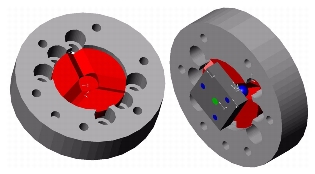
Figure 3.11 Insert Plate in Flange, Sensor Unit on Insert Plate
3.2.2 Preload and Securing Force
The next crucial design element to determine is the method of preloading and securing the "Wonder Wyler" sensor unit onto the corresponding grooves. As mentioned above, the required preload with safety factor is 30 Newtons. Due to the small size of the components, all force application tools would ideally be located in the center of the coupling. Centralizing the force also assists with an even balancing of preload at each ball to groove contact. Three types of securing mechanisms were considered for the sensor unit: physical attachment using a bolt, physical attachment using a "coat hook" style connector, and magnetic attachment. In addition, some quick operating push button fasteners were considered for use, but were discarded immediately due to cost and implementation issues.
Attachment using a Bolt
The simplest and most obvious physical method of securing the sensor unit consists of a single standard bolt that passes through a clearance hole on the unit and threads into a hole at each mounting location. However, several problems became apparent when trying to incorporate bolts within the physical constraints of the sensor unit. As shown in Figure 3.4, one of the inclinometer sensors must be mounted at the center of one coupling triangle, while both sensors make access to the bolt difficult for the other coupling plate. While it is conceivable that the sensors could be rearranged to allow for the bolts to be used, traditional design for assembly rules strongly recommend that obstructed assembly procedures similar to this concept should be avoided. ABB engineers also preferred that some form of quick lock and release ability be available, rather than the lengthy process required to properly preload bolts.
Attachment using "Coat Hook"
During the early stages of design, the second securing concept was formed by ABB engineer Alec Robertson due to the desire to maintain a physical securing connection between the sensor unit and robot at all times. This concept was termed the "coat hook" solution due to the similarity of the attachment element to coat hooks commonly found on airplanes and trains.
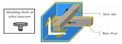
Figure 3.12 Schematic of Coat Hook Design
The construction of this device consisted of a threaded knob that is secured at the center of each groove set on the robot. On the sensor unit, special notches and slots are cut to receive the mounting hook. Springs are incorporated either into the hook or the sensor unit to apply preload force, as shown by the small angled yellow planes in Figure 3.12. Assembly of the device occurs by carefully sliding the hook into the designated slot and lowering the balls into the grooves to allow the springs to apply the preload. While this attachment concept could feasibly be used, complicated design, construction, and assembly procedures preclude the usefulness and novelty of the design.
Magnetic Preload
The final securing solution, a magnet, is generally shied away from in traditional industrial environments due to their tendency to be brittle and pick up ferritic scraps. However, the simplicity and utility of the magnet design superseded these drawbacks for this metrology application. Magnetic preload has successfully been used previously for a metrology application by Federal Products Corporation. In patent 4,574,635, Federal Products used a magnetically preloaded kinematic coupling to secure and support the stylus arm of a surface finish and contour scanner.
Several different magnet types and locations could be used to provide preload for the sensor unit. For the prototype designs, a samarium cobalt disc magnet with 35 Newtons of force was chosen to secure the unit to the robot, but the magnetic force is minimized to keep the Hertz contact stress under 50% of the material limit. CAD and prototypes of this design are shown in Figure 3.13, Figure 3.14, and Figure 3.15.
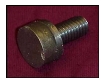
Figure 3.13 Threaded Magnet Unit
The magnet is placed at the center of the coupling circle to evenly provide preload force at each of the ball to groove contacts. To allow some customization of preload force, the magnet was epoxied to a threaded fixture that allowed for a range of motion of several centimeters. Another modification to the prototype design was to include a cylindrical recess at the center of the coupling grooves to accept the magnet unit. As an additional security feature, a safety cable was added to the final magnet design to prevent the sensor unit from falling large distances.
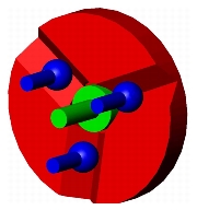
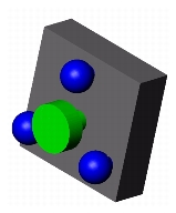
Figure 3.14 Balls and Magnet Coupled Figure 3.15 Sensor Unit Plate 3.2.3 Coupling Location
In addition to the main functional requirement, a side goal was to attempt home position recalibration without removing the tool from the flange. This would greatly reduce the time required to perform the measurements and possibly allow for additional measurements to be performed. By changing the coupling location, major changes to the critical features of the flange could also be avoided.
Flange Edge
One of the simplest ways to attach the "Wonder Wyler" unit to the flange without requiring tool removal is to place coupling grooves on the side of the flange, as shown in Figure 3.16. This arrangement would allow for the sensor unit to easily be placed onto the edge of the flange. During calibration, the axis six joint could be rotated, provided that the tool or robot structure do not interfere with placement.
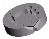
Figure 3.16 CAD Model of Flange with Edge Grooves
While this design would simplify the use of the sensor unit, the manufacturing of three grooves on the edge of a cylinder would be difficult and costly. In addition, the device may interfere with the tool and robot structure.
"Ping Pong Paddle" Design
To avoid manufacturing issues inherent to the edge grooves, an additional design concept was generated to add a ping pong paddle shaped interface plate between the tool and flange. The main new feature of the plate is an arm, or the handle of the paddle, protruding from the side of the flange. Grooves could easily be cast or machined into the front or rear surface of the arm section to allow for coupling of the sensor unit without interfering with the robot structure or tool.
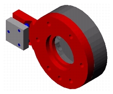
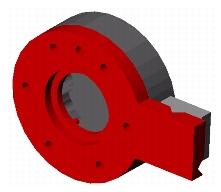
Figure 3.17 Paddle Flange Plate with Sensor Unit on Front Mount Figure 3.18 Paddle Flange Plate with Sensor Unit on Rear Mount
Figure 3.17 and Figure 3.18 show the two possible configurations of the ping pong paddle design with sensor unit attached. To use the interface plate, two separate three pin couplings would attach the interface plate to the flange and the tool to the interface plate. Another possibility is to replace the existing flange with a ping pong paddle shaped flange, which removes the stacked couplings. However, this concept was discarded as the arm could interfere with the robot structure at extreme positions of the last two axes as well as interfere with objects in the robot's workspace.
3.2.4 Dynamic Axis 1 Application
The final major concern for designing the couplings for the sensor unit was the measurement of the axis 1 rotation. Since the joint axis is parallel to the gravity vector, rotation of the joint with the sensor unit mounted anywhere on the robot will not cause any deviation in the measurement of axis rotation. Typically, this sort of measurement is performed with a scale mounted on the edge of the cylindrical axis or a rotary encoder. Engineers at ABB developed several solutions to measure the axis rotation, including a mechanical fork and a hinged plate. The mechanical fork operated as merely a physical stop for the robot, while the hinged plate method combined a physical transfer with the measurement features of the sensor unit. To measure the rotation of the axis, a kinematic linkage transfers the rotary motion to a tilt of the sensor unit in a measurable direction. However, these designs were not accurate enough for the measurement requirement.
As an alternative design, Torgny Brogardh of ABB suggested a new concept called the "dynamic V-groove" variation on the standard coupling. Mounted inside the cube, the two inclinometers measure the roll and pitch angles with respect to the gravity vector. The sensor unit is placed on the "dynamic V-groove," shown in Figure 3.19, which converts the axis rotation parallel to gravity to a rotation that can be measured by the inclinometers.
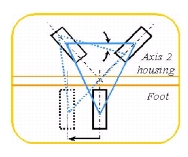
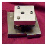
Figure 3.19 Schematic of Dynamic Groove Figure 3.20 Dynamic Groove Prototype
Furthermore, the design of the groove-sphere interface causes large inclinometer measurements from small axis motions, resulting in improved calibration accuracy. This is particularly important for larger robots where a small angular error is dramatically magnified at the robot flange resulting in large positioning errors. During the design of the dynamic coupling, a major concern was that the coupling would remain stable throughout the full motion of the device. However, the required working range of the relative motion was sufficiently less than required to cause instability. A prototype of the dynamic groove was created to check the theoretical geometry checks for stability. As shown in Figure 3.20, the two coupling halves can be moved relative to each other in two directions without causing instability. To ensure that the dynamic groove plates would be compatible with the robot geometry, a CAD model of the complete system was created as shown in Figure 3.21.
Figure 3.21 CAD Model of Dynamic V-Groove System
3.3 Physical Prototypes
In order to test out the functionality of the Wonder Wyler unit, two prototypes were constructed. The first prototype consisted of several plates bolted together, while the second prototype is a one piece, high quality machined part. The second prototype was constructed by ABB and represents the final product with only minimal changes.
3.3.1 First Prototype
Description of Prototype
The first prototype follows closely with the design development description above and consists of an open cube structure of three plates. One side plate and the bottom plate have three half inch tooling balls press fit in the coupling triangle, with a coupling circle radius of 20 mm. At the center of the coupling triangle, the threaded magnet unit is mounted in a threaded hole to provide the 35 Newton preload. These prototypes were manufactured with tolerances on the order of 0.01 mm in tool steel. For connection to the flange, a grooved insert plate was made with a sliding fit. Additional grooves for the dynamic V-groove plates and other attachment plates were manufactured at ABB and attached to existing bolt holes. To avoid lengthy alignment of the groove plates, all measurements using the initial prototype were taken relative to the first measurement to ascertain the effect of only the ball and groove coupling and disregard the relative mounting of the groove to the robot. Figure 3.22 and Figure 3.23 show the completed Wonder Wyler sensor unit.
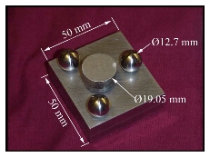
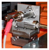
Figure 3.22 Side Plate of Sensor Unit Figure 3.23 Complete Sensor Unit
Testing and Measurement
During testing, the sensor unit was placed on each coupling mount and each axis was moved until the sensors reported the predefined value. Several repetitions of the measurement process provided repeatability of the home position between 0.15mm to 0.35mm. This value represents a significant increase over the current levelling system and averages to within the required accuracy of 0.2 mm. In Figure 3.24, each mounting plate is shown along with the sensor unit in place in the grooves.
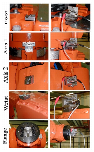
Figure 3.24 Testing of Sensor Unit
3.3.2 Final Product
The mounting repeatability of the kinematic coupling interface offers micrometer accuracy for both horizontal and vertical placements. However, error still remains within the sensor unit greater than the desired 0.2 mm recalibration error, due to variation between individual cubes caused primarily by machining tolerances of the three cube surfaces. This final issue is addressed in the completed design of the product prototype shown in Figure 3.25.
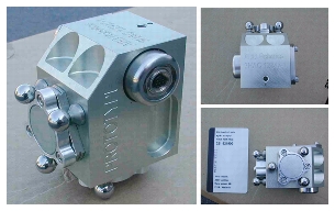
Figure 3.25 Final Prototype of Sensor Unit
To remove the inaccurate assembly of the separate plates, a single piece of Aluminum is used as the chassis for the cube. Only three outer surfaces are required to be accurate hence enabling the entire cube to be machined in a single pass with an NC milling machine. Furthermore, the mounting of the sensors on the outer surface of the cube reduces the size of the structure to approximately that of a credit card, reducing weight and allowing the cube to be used in robots with smaller accessible calibration areas. The product prototype is integrated with existing large robots through an add-on kit wherein the V-groove plates are permanently bolted to the robot structure. For optimal cost and performance V-grooves are directly machined into the robot structure on newer robot models. The results of recalibration tests satisfy the original specifications, revealing an error of 0.2mm, which represents a five-fold improvement on the existing system.