Chapter 1
Introduction
1.1 Motivation
In the measurement and instrumentation fields, kinematic couplings (KCs) have been widely used as a method to create precise and repeatable interfaces on a variety of devices. These devices, such as optical lenses and probe mounts, require extremely high repeatability while subjected to small disturbance loads in ideal environments. Because of the strict requirements couplings place on their environments, their use in industrial settings has been relatively limited to clean areas such as semiconductor production facilities and imaging device assembly. Traditional factory environments present less ideal conditions for couplings, but equipment used in these settings could benefit greatly from improved repeatability. Although the semiconductor industry level of precision is not always necessary for general industrial machines, designers are continually increasing the stringency placed on the dimensions of their parts. In order to produce these parts, designers require better and better precision from the manufacturing equipment and machine tools. Incorporating kinematic couplings into the equipment can allow exchangeable interfaces to be more repeatable while minimally increasing the machine cost.
A prime example of this trend exists in the robotics industry. Typical industrial robots are used in the automobile industry to assemble, weld and paint cars, as well as general material handling in other industries. In these examples, small errors in the geometric properties are amplified by the robot structure and cause larger errors in the parts. The geometric errors inherent to the robot structure are removed using calibration before the robot leaves the production facility. However, the initial calibration degrades with time due to changes in the resolver settings, thermal changes, increased loading, etc. or from discrete alterations to the robot structure. Common alterations include replacement of an individual motor or of the wrist module.
To restore the robot to optimal operation, an onsite calibration is performed. This type of calibration currently requires running the robot through a series of motions while recording the robot's Tool Center Point (TCP) with some type of measurement system. In the measurement control system, complex calculations are carried out to formulate a set of error parameters, which are used by the robot controller to correct the robot's motion. While calibration can remove most of the errors from a robot system, it requires a lengthy process of measuring a hundred or more points that can drastically reduce the productivity of a assembly line or an individual robot for up to several hours. Several hours of downtime can represent thousands to millions of dollars in lost revenue. By incorporating KCs into the robot's structure, the requirements of the calibration procedure and measurement system can be reduced significantly. The addition of KCs to an interface improves the repeatability of the connection while often decreasing the complexity of the interface features.
1.2 Thesis Scope and Organization
This thesis will present a basic overview of the standard kinematic coupling design process, as well as a design formulation for a newer type of coupling named the three pin coupling. In addition to the design process, a shopping list of concerns for attempting KC implementation in an industrial application.
Both the design process and industrial concerns will be illustrated using two case studies of KC application on the IRB 6400 Industrial Robot available from ABB Robotics, shown in Figure 1.1.
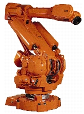
Figure 1.1 ABB IRB 6400 Robot
The first case study follows the development of a small scale removable device nicknamed the "Wonder Wyler" unit, which is used to calibrate the rotary resolvers on each motor. To use the device, a magnetized kinematic coupling secures the unit to the robot for initial calibration before the robot leaves the production facility and for subsequent recalibrations after a major structural change such as a motor replacement. The magnitudes involved in this application include forces of around 30 N with a device size of approximately a 50 mm cube.
The second application details an effort to improve the repeatability of the wrist to upper arm interface on the IRB 6400 Robot. The wrist unit of the robot consists of two motors for the last two degrees of freedom of the robot's six degrees and the interface from robot to tool. The existing coupling constrains the interface using a pinned joint, which signifies that the repeatability of the coupling is determined solely by the tolerancing of the joint features. By incorporating kinematic coupling features into the interface, the repeatability of a wrist interface becomes a function of items such as surface finish and preload, while only the interchangeability of separate interfaces remains as a function of the tolerances. While the functioning of the external calibration device depends mostly on the environmental quality, the second application combines the effects of a detrimental environment with those of a medium-high loading situation. The magnitudes involved in this application include forces of around 30,000 N with an interface size of approximately 200 mm by 200 mm.
Thesis Organization
The second chapter will present the basics behind coupling design, as well as the problems to be addressed in a factory setting. Chapter three moves into the small scale coupling design, with a detailed description of the design development. The fourth chapter addresses the design of the medium scale coupling. The final chapter will present some conclusions and suggestions for future work. Rather than pepper this document with references and formulas, the appendices contain a list of references grouped by the technical area and several sets of formulas presented to further explain the design process.