
2.007 Controller & Wiring (2008)
The 2.007 Control System has been updated for 2008. The core functionality and circuitry has not changed: It is configured to wirelessly control up to four motors per control box and to use the 2.007 kit drill battery as its power supply. The control box enclosure and connectors are new this year, so please read the wiring information, especially regarding the motor connector, on this page carefully before wiring your robot. Additionally, each podium now has an on-board PC running the control software. Useful robot telemetry is displayed on an embedded screen and can be recorded to a flash drive for use in analysis.
Please direct any questions about the 2.007 Control System to this email.
Contents:
System Overview
Dimensions, Mounting, and CAD Model
Connector Wiring Info
IMPORTANT: Motor Connector Wiring Note
Pinout/Polarity
Gamepad Command Mapping
Wiring a 2WD Robot
Wiring a 4WD Robot (four motors)
Dashboard
Data Logging
System Overview:
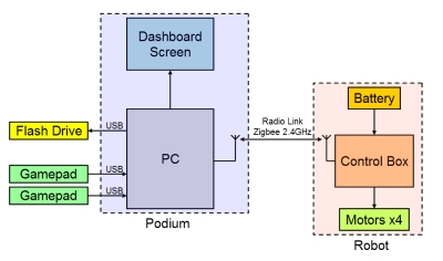
The image above represents the control flow for a single podium and control box. Each podium has multiple control boxes of the same channel, indicated by the color of the podium and of the tape on the control boxes. The system is intended for one box per channel to be on at any given time. If multiple boxes of the same channel are on, each will receive motor commands, but telemetry reported back from the boxes will be unreliable.
Dimensions, Mounting, and CAD Model:
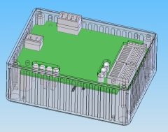
You can download a detailed SolidWorks assembly of the 2.007 control box here.
The control box LxWxH is 4.322"x3.223"x1.795", with the height measured from the bottom of the box to the top of the 8-pin motor connector. It weighs 200g.
Mounting Considerations: You are free to mount your control box anywhere within your robot, though it must still satisfy the overall size restriction. Mounting must be done in a way that is sturdy, but also allows quick attachment and detachment in between rounds of the competition. (See the rules for setup time restrictions.) Mounting solutions must not alter the control box in any way. Do not use glue, tape, or adhesive of any kind to attach the control box to your robot, even during practice in the lab! If you are caught doing this, you will have to remove any adhesive residue completely. Use rubber bands, velcro straps (not adhesive-backed velcro) or mechanical latches to hold the box in place instead. Also, remember that enclosing the control box in metal will decrease radio performance.
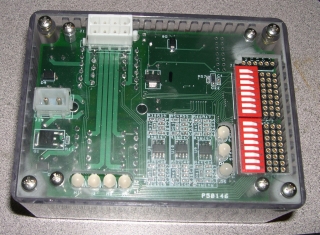
Connector Wiring Info:
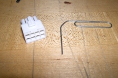
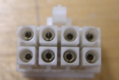
The picture above of the top left corner of the control box shows both the 2-pin battery and the 8-pin motor connector on the 2.007 control box. Mating connectors are provided in the kit, along with quick disconnect terminals for the drill battery. Read these instructions carefully, as there is a limited supply of spare mating connectors.
Wiring Process: In the kit, you will find metal crimp terminals and plastic housings for each connector. 16-gauge twisted-pair red and black wire is available on spools in the lab. Soldering irons, solder, and wire cutters, strippers, and crimpers are also available in the lab. To make a connector, first cut wire of the appropriate length and strip the ends approximately 0.25". First crimp, then solder the stripped ends of the wire into the crimp terminals. Before inserting terminated wire into the plastic housing, test your connection on the control box by directly attaching the terminals to the control box pins. (Be careful that they do not short circuit by touching each other. Use electrical tape.) Only when you are sure that the connections and polarity are correct, fully insert the terminated wire into the plastic connector housing.
Good Wiring Practices handouts for battery connectors, motors and how to solder.
If you put your motor wire into the wrong spot in the plastic housing, do not throw it away! Pin extractors are also available in the lab at the wiring station. Additionally, you could cut and splice the motor wires themselves.
IMPORTANT: Motor Connector Wiring Note:
The crimp terminals for the 8-pin motor connector are a very tight fit to their mating pins on the control box. For this reason, it is important to make sure that they are fully inserted into the plastic connector housing. The fish hooks on the crimp terminal must click into place inside the plastic housing. If not, the connector insertion force will push the terminals back out of the housing.
To ensure the terminals are fully inserted, push them in from behind with a lot of force using a small allen wrench and try pulling them out. It is also very helpful to widen the terminals a bit. Use only the paper clips provided in your kit (Office Depot jumbo paper clips, left picture above). Insert and remove the end of a clip into each terminal opening while in the plastic housing (right picture above). It should go in about 1/4". If it pushes the terminal out the back of the connector, the terminal was not fully inserted. After "paper-clipping" all the terminals, the connector will be a looser, but still snug, fit to its mating connector on the control box.
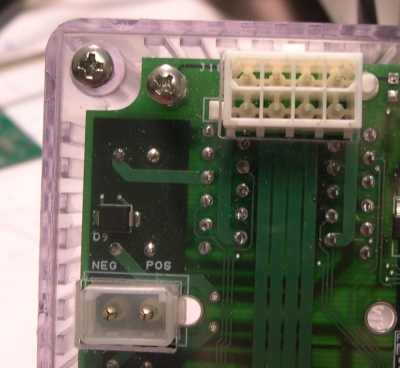
Pinout/Polarity:
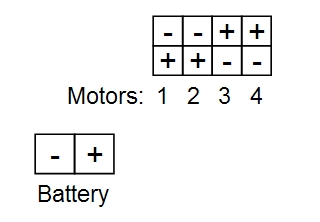
The diagram above, seen from the perspective of looking down on the top cover of the control box, shows the controller pinout.
Battery: The battery connector polarity is also indicated by a "POS" and "NEG" designation on the circuit board. On the Black & Decker 18V drill batteries, the outer terminal is positive and the inner terminal is negative. If the battery polarity is reversed, the control box will not turn on, but it is protected against permanent damage.
Motors: The motor pinout is often a source of confusion and miswiring, so please be sure to test your connections before putting wires into the plastic connector housing. In the diagram, the pins labeled with a "+" will receive a positive voltage when given a "forward" command from the control software. How this translates to motor rotation direction depends on how the motor wires are connected to these terminals. See the motor polarity information for details. Also, see the gamepad mapping below for how gamepad joystick and buttons are mapped to motor commands.
Gamepad Command Mapping:

This image is also available on-screen at each podium.
Each podium has two numbered USB gamepad controllers. Gamepad #1 is configured for differential steering with either two motors (1 and 2) or all four motors. Gamepad #2 is configured for two-joystick drive where each joystick's Y-axis independently controls the single motor indicated. Both gamepads can also control motors digitally (on or off only, no speed control) using the four top buttons. Both gamepads can be used simultaneously, and it is encouraged to take advantage of this by having a co-driver.
Differential Steering: Also referred to as "skid steering" or "tank steering," differential steering means that the wheels on opposite sides of a robot can be driven at different speeds to cause the robot to turn. Gamepad #1 is configured to command either two or four motors for differential steering with a single joystick. The Y-axis sets the common command, adjusting the overall forward or backward speed, and the X-axis sets the differential command, adjusting the rate of rotation. Using both, the robot can move in a straight line, a sweeping curve, or a zero-radius turn. The differential command is added to the left motor and subtracted from the right motor. As a result, both motor polarity and motor "side" matter.
For two-motor differential steering, the Motor 1 output should be wired to the left side motor so that pushing up or right on the left joystick of Gamepad #1 causes the left wheel to move forward. The Motor 2 output should be wired to the right side motor so that pushing up or left on the left joystick of Gamepad #1 causes the right wheel to move forward.
For four-motor differential steering, the Motor 1 and 2 outputs should be wired to the left side motors so that pushing up or right on the right joystick of Gamepad #1 causes the left wheels to move forward. The Motor 3 and 4 outputs should be wired to the right side motors so that pushing up or left on the right joystick of Gamepad #1 causes the right wheel to move forward.
Dashboard:
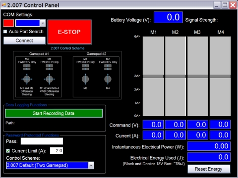
This is the on-screen display at each podium.
The dashboard program displays useful information from the 2.007 Control System on screen at each podium. The best way to get familiar with the display is to use it for practice. Below is a quick run-down of the on-screen display.
COM Settings: You should not have to do anything to these. The small box in the upper-left corner of the window indicates COM status: red is disconnected, yellow is connected, waiting for a control box to turn on, and green is connected and communicating with a control box. If the box is yellow, simply plug in a control box to connect. If the box is red, check "Auto Port Search" and click "Connect" to begin searching for a control box. Then, plug in a box to connect.
E-STOP: If your robot is out of control and you want to immediately stop all four motors, click this button. It will turn dark red and disable any further control until you click "Disconnect" and "Connect" to reset the system.
Battery Voltage: The measured voltage of the drill battery. A fully-charged 18V Black & Decker drill battery could be well above 19V. Below 17V, the battery may need recharging. The motor drivers will turn off below 10V, although the controller and radio will remain on down to 5V.
Signal Strength: A direct measurement of the strength of signals received, from the point of view of the control box. The podium is fitted with a high-power transmitter while the box has a low-power radio, so the signal from the podium to the box will be stronger than the return signal. This indicator reflects the stronger podium-to-box signal.
Motor Indicators: Labeled "M1" through "M4," the bars display two pieces of information for each motor: The gray line reflects the voltage command and the blue bar (not pictured) represents the measured current for each motor. The current scale is shown to the left of the bars. Numeric indicators for voltage command and current are shown below each bar.
Power and Energy: Both the instantaneous electrical power draw and accumulated electrical energy are displayed. These are calculated directly from the voltage and current measurements for all four motors. Pressing "Reset Energy," reconnecting, or starting a new data recording session will reset the energy meter.
Data Logging:
Of course, most of the time while driving you will be looking at your robot, so the dashboard program can also record data into a comma-delimited text file. You can save this on a flash drive (use the free USB slot on the podium cover) and import it into Excel, MATLAB, and other programs for later analysis.
To record data, insert your USB flash drive into the available slot on the podium cover. You can start recording before or after you connect a control box. Click "Start Recording Data" and navigate to your flash drive. Select an existing file or type the name a file you wish to create. The default extension is .txt. Data recording will begin when you select a file and a control box is connected. Data recorded includes time, battery voltage, signal strength, motor voltage commands and currents, instantaneous electrical power, and integrated electrical energy. The file created is a comma-delimited text file, which can be loaded into any spreadsheet or mathematical analysis software package. To stop recording, click "Stop Recording Data."