
2.007 Motor Information (2008)
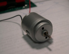
Mabuchi RC-260RA-2670 Brushed DC
Motor
The 2.007 kit motors (packaged with the Tamiya planetary gearbox
sets) are Mabuchi model number RC-260RA-2670
brushed DC motors. The gearbox set is Tamiya model number
72001. You can view the Mabuchi motor datasheet
here:
http://www.mabuchi-motor.co.jp/ja_JP/cat_files/rc_260rasa.pdf
However, the Mabuchi datasheet specifications are not reflective of actual, in-system performance due to differences in operating voltage and source impedance of the 2.007 Controller. Similarly, testing motors on a power supply is not reflective of actual in-system performance. All specifications on this page are adjusted, in-system specifications.
Questions about motor specifications can be sent to this email.
How does a DC motor work? Notes are here, courtsey of Paul Sclavounos.
Contents:
Quick Specifications
Wiring Polarity
Torque-Speed
Curve
Sample Calculation
Motor
Tips
Detailed Specifications
Quick Specifications:
Specification |
Unit |
Value |
Operating Voltage Range (details) |
V |
+/- 6.0 |
No-Load Speed @ 6.0V (details) |
RPM |
24000 |
Maximum Mechanical Power @ 6.0V |
W |
4.4 |
|
Total Series Resistance |
Ω |
1.7 |
Torque Constant (details) |
mN-m/A |
2.0 |
Stall Current @ 6.0V (details) |
A |
3.5 |
|
Stall Torque @ 6.0V (details) |
mN-m |
7.0 |
Current Limit (details) |
A |
2.0 |
|
Current-Limited Torque (details) |
mN-m |
4.0 |
|
Single Gear Stage Efficiency* (details) |
% |
85 |
*Note: Gear stage efficiency varies widely
and is dependent on good gearbox assembly and constraint.
Wiring Polarity:
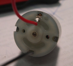
Applying a positive voltage differential from red wire terminal, also marked with a (+) on the molded plastic backing, to the black wire terminal will cause the motor shaft to spin with an inward velocity vector. (Counter-clockwise as viewed from the perspective of the image above.) Reversing the voltage will reverse the direction of spin. Keep in mind that drive motors connected to wheels on opposite sides of your robot will require opposite spins for the robot to go straight.
(See the 2.007 Controller instructions for more polarity information.)
Good Wiring Practices handouts for battery connectors, motors and how to solder.

Sample Calculation:
What is the maximum available torque from a 100:1 gear
reduction? What will be the output speed at this torque?
1. The motor's
maximum torque occurs at the current limit of 2.0A. From the
torque-speed curve, this is 4.0mN-m at
10000RPM.
2. The 100:1 gear reduction will
divide the speed and multiply the torque. So, in the ideal
situation with 100% efficiency, the output torque will be
400mN-m and the output speed will be
100RPM.
3. Gearbox efficiency is usually accounted for as a
reduction in torque. A 100:1 reduction requires
3 gear stages, so using an efficiency of 0.85
per stage, the reduction factor would be 0.85^3 = 0.614.
Multiplying this by the ideal output torque gives the realistic output torque of
246mN-m.
1. When designing, aim to be somewhere between the max power and max speed on the torque speed curve (the right half in the chart above). This is the most electrically efficient operating range. To do this, work backwards through the calculation: Start from your expected load, go through the gear reduction (including mechanical efficiency), to the torque that the motor will see. Then compare it to the torque-speed curve. Never design in the high torque, low speed range of the curve, as both power and electrical efficiency will suffer. If you find that your design falls in this range, move to a higher gear ratio.
2. The 2.007 Controller actively measures motor current, as well as other data, and displays it on-screen at the podium. You can also record the data onto a flash drive and analyze it later. The data can be used to calculate where on the torque-speed curve your motors are operating. If, for example, your motors are hitting the current limit of 2.0A, you either need to improve efficiency (check gearbox assembly) or move to a higher gear ratio.
3. Wire carefully. Nothing is worse than having a motor wire pull out during the competition. Strain relieve all wires with zip-ties and/or electrical tape. (See the wiring guide for more tips.)
4. The motors overheat easily and can be permanently damaged. Do not run them for more than a few minutes at a time and monitor the temperature often. Give them time to cool off in between runs. Also, do not block the vent holes on the motor.
Detailed Specifications:
Operating Voltage Range: +/-6.0V
The
2.007 Controller actively measures the battery voltage and scales motor commands
appropriately. So, with an 18V battery, a "full forward" command sends the motor
1/3 of the full voltage, or 6.0V. If the battery voltage is higher or lower, it
will scale the command appropriately to maintain the proper voltage
range. If the battery voltage falls below 10V, the motor drivers will turn
off. Scaling is done by pulse width modulation, so the motor actually sees a
square wave with a duty cycle equal to the scaling fraction. This is done at
about 20kHz, fast enough for the motor to run smoothly.
No-Load Speed @ 6.0V: 24000RPM
This is
how fast the motor will spin given a "full speed" command of 6.0V. The speed
scales proportionally to the voltage command.
Maximum Mechanical Power @ 6.0V:
4.4W
Note that this is below the maximum power that one would calculate from
the Mabuchi datasheet (6W) even though the operating voltage is higher. This is
because the motor's extremely low resistance makes it hard to supply
adequate power from a small-scale controller. See the next section on resistance
for a more thorough explanation.
Total Series Resistance: 1.7Ω
The
resistance of the motor winding alone is 0.7Ω, which is extremely low for a
motor of this size. The motors are designed to draw a lot of
current at a low voltage for operation in small, AA battery-powered devices.
They are not designed to be run off of an 18V drill battery. (In fact,
if you try this and stall the motor, you will draw about 20A and
probably instantly fry the motor.) In order to use them, the 2.007
Controller must appropriately scale the voltage to a more reasonable level, and
the circuitry required to do so adds to the total resistance of the system. So,
the actual resistance of the entire system (battery, controller, and motor) is
closer to 1.7Ω. This means that, when operating near stall, more power is
dissipated in the control circuitry than in the motor itself. This also
means that the total available power is lower than is indicated in the Mabuchi
datasheet.
Torque Constant: 2.0mN-m/A
This is a
property of the motor, determined by the windings and magnets. It indicates how
much torque is generated per Amp of current drawn.
Stall Current @ 6.0V: 3.5A
This is
simply 6.0V divided by 1.7Ω. This is how much current is drawn when a 6.0V
command is sent and the motor shaft is not allowed to move. Note that this
is not the same as applying 6.0V directly to the motor terminals from a power
supply, because of the extra resistance added by the battery and control
circuitry. In fact, if you apply a 6.0V command and stall the
motor, the measured voltage across the terminals will be closer to
2-3V because of the other resistive losses. The motor drivers used in the 2.007
Controller are rated for up to 3A of continuous current, though they will heat
up significantly. For this reason, a current limit is utilized (see below).
Stall Torque @ 6.0V: 7.0mN-m
This is
3.5A multiplied by 2.0mN-m/A. This is the torque the motor will
produce when stalled out at 6.0V, but does not reflect the available
torque because of the current limit.
Current Limit: 2.0A
This limit is set by
the control software to protect both the motors and the control circuitry from
overheating. As the current limit is hit, the software will scale back the
voltage command. The current limit is set above the maximum power point on the
torque speed curve, so it does not restrict power available to your design, only
torque (see below). Choose your gear ratios appropriately to utilize the power
available.
Current-Limited Torque: 4.0mN-m
This is
just 2.0A multiplied by 2.0mN-m/A. This is the maximum torque the motor will
produce at the current limit. It should be used as a high constraint for design.
(Ideally, mechanisms should operate below this point on the torque-speed
curve.)
Single Gear Stage Efficiency:
85%
This number can vary greatly (usually lower) depending on how
well your gearboxes are assembled and lubricated. It is multiplicative, so a
gear reduction with n stages could have a total efficiency of
0.85^n.